
01 · Device purpose
Compact Energy Storage for Short-Duration Events
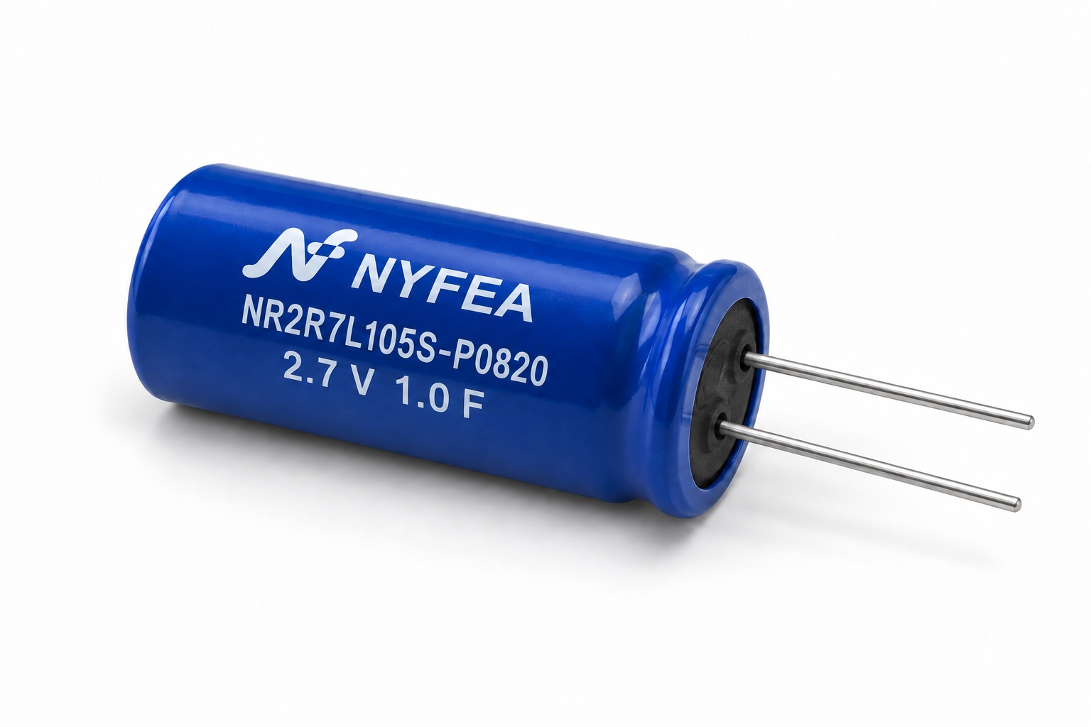
NR2R7L105S-P0820 stores energy electrostatically rather than chemically. Its 1.0 F capacitance, low leakage and radial-lead format make it suitable for local hold-up functions where a rechargeable battery would be oversized, too slow to charge or unnecessary.
Typical use is to bridge a brief supply interruption, supplement a controlled current pulse, retain information during battery exchange, or accumulate small amounts of harvested energy before a low-power load wakes up.
- Radial lead format: two 0.6 mm leads on a 3.5 mm pitch for through-hole assembly.
- Compact body: 8.0 mm nominal diameter and 20.0 mm nominal length.
- Pulse capability: 0.54 A maximum working current at ΔT = 15 °C and 2.32 A maximum peak current.
- Low leakage: 0.01 mA maximum after the specified 72-hour condition.
- Environmental range: -40 °C to +70 °C operating range.
Selection boundary: This is a polarized low-voltage energy-storage component. It is not a high-voltage energy-storage module, a direct replacement for a battery, or a safety-rated backup source.
02 · Selection guide
When This 2.7 V, 1.0 F Part Is a Good Fit
| Design question | What to check | NR2R7L105S-P0820 implication |
|---|---|---|
| Is the system rail 2.7 V or lower? | Maximum capacitor voltage including charge tolerance and transients | Do not exceed the 2.7 V rated voltage. |
| How much hold-up energy is required? | Load power, allowed voltage drop and hold-up time | Use the capacitor-energy equation and validate at the actual discharge endpoint. |
| Is pulse current within range? | Peak current, repetition rate and temperature rise | Compare with the 0.54 A working-current and 2.32 A peak-current limits. |
| Is the load voltage-sensitive? | Minimum operating voltage of the downstream circuit | Usable energy is lower than full stored energy when the load needs a high minimum voltage. |
| Is board space constrained? | Body clearance, lead pitch and insertion direction | Allow for φ8.0 mm body diameter, 20.0 mm body length and lead-forming clearance. |
03 · Electrical
Electrical Characteristics
The values below are component-level specification values. In an assembled product, effective hold-up time also depends on wiring resistance, switching loss, load profile, temperature and the discharge cutoff voltage.
| Parameter | Specification | Unit | Design relevance |
|---|---|---|---|
| Rated voltage, UR | 2.7 | V | Maximum continuous working voltage. |
| Nominal capacitance, C | 1.0 | F | Energy-storage starting point; tolerance applies. |
| Capacitance tolerance | -20 to +50 | % | Use the low-end capacitance for guaranteed hold-up calculations. |
| Operating temperature | -40 to +70 | °C | Validate the complete assembly across this range. |
| Max ESR, RAC at 1 kHz | 95 | mΩ | Contributes to pulse voltage sag and self-heating. |
| Max leakage current after 72 h | 0.01 | mA | Important for always-on and energy-harvesting designs. |
| Max working current, ΔT = 15 °C | 0.54 | A | Use for repetitive current budgeting. |
| Max peak current | 2.32 | A | Check pulse duration and repetition rate in the final design. |
| Max stored energy | 0.0033 | W·h | Full-voltage energy reference from the specification. |
| Energy density | 2.70 | Wh/kg | Component comparison metric. |
| Power density | 2525.7 | W/kg | Component comparison metric. |
04 · Energy planning
Stored Energy, Voltage Sag and Hold-Up Time
A supercapacitor releases energy as its voltage falls. The ideal relationship is E = ½CV²; however, use the PDF-listed maximum stored-energy value of 0.0033 W·h as the controlled document reference for this part. Validate usable energy in the target circuit using its actual cutoff voltage, load profile and worst-case capacitance.
| Calculation | Expression | Engineering use |
|---|---|---|
| Datasheet stored-energy reference | 0.0033 W·h maximum | Use the released specification as the traceable component reference. |
| Usable energy to a cutoff voltage | ½C(Vstart² − Vcutoff²) | Use this for actual hold-up sizing. |
| Initial ESR voltage step | ΔV ≈ I × ESR | Estimate immediate pulse sag; include PCB and switch resistance. |
| Ideal constant-current discharge time | t ≈ C(Vstart − Vcutoff) / I | First-pass estimate only; validate with the real load. |
Important: A downstream converter may stop operating well before the capacitor is fully discharged. Base system calculations on the converter's undervoltage threshold, the minimum load voltage and worst-case capacitance rather than on 1.0 F nominal alone.
05 · Mechanical
Body Dimensions and Polarity
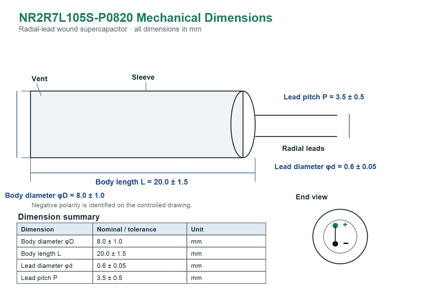
Keep body, lead and assembly clearances in the PCB library. The lead pitch and diameter should be confirmed against the controlled drawing before releasing a through-hole footprint.
| Dimension | Nominal / tolerance | Unit | Footprint consideration |
|---|---|---|---|
| Body diameter, φD | 8.0 ± 1.0 | mm | Allow mechanical keep-out around the sleeve. |
| Body length, L | 20.0 ± 1.5 | mm | Allow for body-end and lead-forming clearance. |
| Lead diameter, φd | 0.6 ± 0.05 | mm | Select a plated-hole size compatible with the finished process. |
| Lead pitch, P | 3.5 ± 0.5 | mm | Use the controlled pitch when releasing the land pattern. |
Confirm the negative terminal orientation from the controlled drawing before PCB placement and automated insertion.
06 · Part number
NR2R7L105S-P0820 Part-Number Format
The product code communicates the series, rated voltage, construction, capacitance code and mechanical size family. Confirm the complete approved ordering code with NYFEA before purchasing release.
| Segment | Meaning | Value in this part |
|---|---|---|
| NR | Series / radial wound family | NR |
| 2R7 | Rated voltage | 2.7 V |
| L | Wound construction code | L |
| 105 | Nominal capacitance code | 1.0 F |
| S | Capacitance tolerance code | S, -20% to +50% |
| P08 | Diameter family | 8 mm |
| 20 | Body length family | 20 mm |
07 · Test methods
Capacitance, ESR and Leakage Verification
Comparison data is meaningful only when the charge state, test frequency, temperature and measurement timing are controlled. Use the released specification for the exact acceptance sequence and laboratory condition.
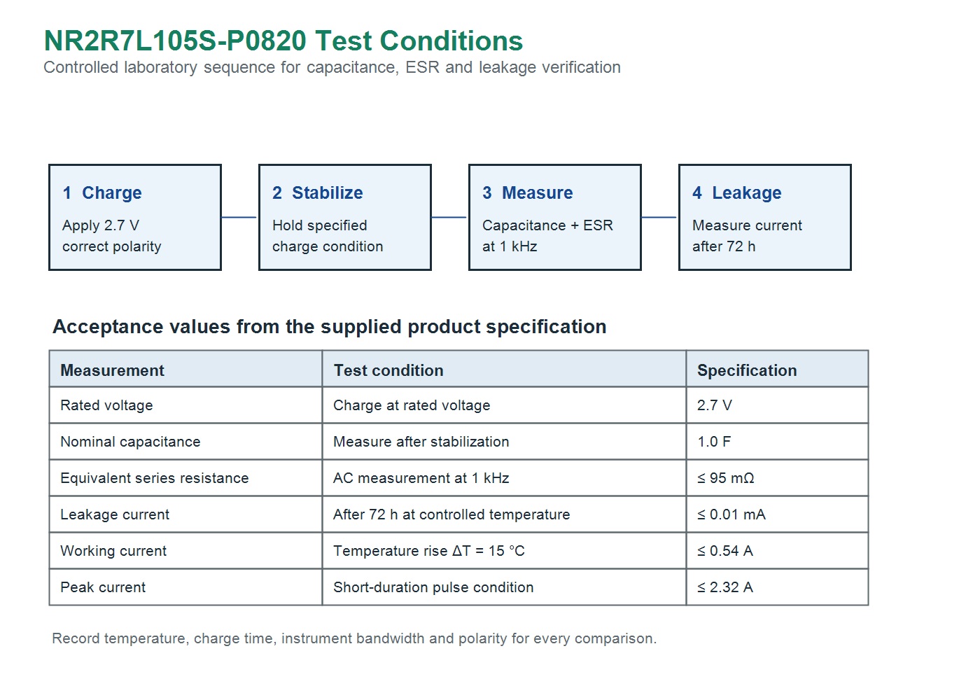
- Polarity first: charge only with the correct terminal orientation and never use reverse voltage as part of a test setup.
- Use the stated frequency: compare ESR values at the specified 1 kHz AC measurement condition.
- Allow stabilization: record time after charge and ambient temperature with each result.
- Capture the real system load: bench-test pulse performance using the finished board, cable and power-path resistance.
08 · Circuit integration
Charging, Discharge and Protection Design
The capacitor should be integrated as a managed energy-storage node, not simply placed across a supply rail. Add a controlled charge path and a predictable discharge path so the stored energy cannot create an unintended system state.
| Function | Recommended design treatment | Reason |
|---|---|---|
| Initial charging | Use a current-limited charge path. | Reduces inrush current and protects the upstream source. |
| Overvoltage prevention | Maintain margin below 2.7 V, including tolerance and transients. | Protects the polarized capacitor from excessive working voltage. |
| Reverse-voltage prevention | Use diode, ideal-diode or controlled-switch architecture as appropriate. | Reverse voltage can damage a polarized supercapacitor. |
| Controlled shutdown | Provide a discharge path or load switch that leaves the system in a known state. | Stored energy may otherwise keep portions of the circuit partially powered. |
| Series connection | Use a balancing strategy and review the complete system with NYFEA. | Individual capacitor voltage may become uneven in a series stack. |
09 · Assembly
PCB Layout, Insertion and Soldering Considerations
Mechanical stress and uncontrolled soldering heat can reduce reliability. Treat the sleeve and lead seal as functional interfaces that should remain undamaged through the complete assembly process.
- Mark polarity clearly: place a visible PCB polarity mark at the component location and include it in inspection documentation.
- Keep leads relaxed: do not force lead spacing, twist the body or apply bending stress at the seal after insertion.
- Control soldering energy: use the qualified soldering profile and avoid excessive tip contact time or direct heating of the sleeve.
- Maintain clearance: keep the body away from heat-generating parts, sharp enclosure features and moving assemblies.
- Support the board: account for vibration and handling loads if the product is used in portable or industrial equipment.
- Inspect after assembly: check polarity, sleeve condition, solder fill and any signs of mechanical damage before power-up.
10 · Reliability
Temperature, Humidity and Storage Boundaries
Performance and life are system-dependent. The supplied specification provides environmental and life-test references; production release should include the actual PCB, enclosure, charge voltage and load profile.
| Area | Specified boundary | Design action |
|---|---|---|
| Operating temperature | -40 °C to +70 °C | Validate capacitance, ESR and leakage at the application extremes. |
| Endurance / life | Use the controlled PDF life-test conditions | Recheck capacitance, ESR and leakage after qualification exposure. |
| Humidity | 90% to 95% RH, 240 h test | Prevent condensation, contamination and corrosive exposure in the assembly. |
| Storage | Cool, dry, clean environment | Keep away from heat, moisture and corrosive gases; observe approved stock-control rules. |
11 · Handling
Use Precautions
- Never apply reverse voltage or exceed the 2.7 V rated voltage.
- Do not use in high-frequency rapid charge/discharge circuits without thermal, ESR and lifetime validation.
- Provide current limiting, overvoltage prevention and a safe discharge path in the finished circuit.
- Keep the capacitor away from corrosive gas, condensation and sustained high humidity.
- During soldering, control tip temperature, contact time and board preheat to avoid overheating.
- Do not press, puncture, crush, twist or sharply bend the body or leads after installation.
- Do not short the terminals with a conductive tool; discharge stored energy safely before service or rework.
12 · Applications
Typical Application Contexts
These are representative engineering contexts, not end-product approvals or safety certifications. Use the selection and integration guidance above to validate each case.
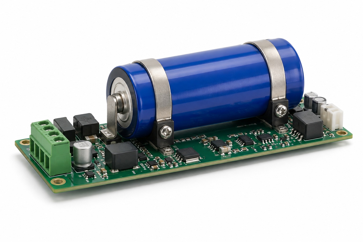 Backup PowerMaintain a low-power rail long enough for orderly state retention or shutdown.
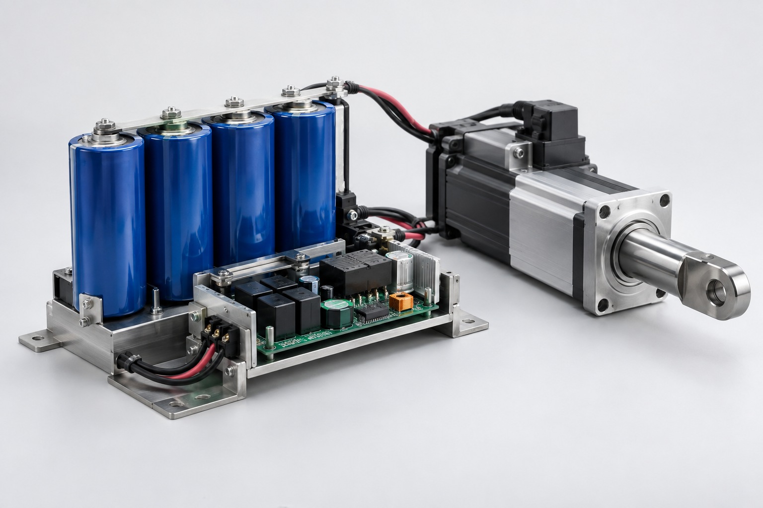 Pulse PowerAssist a short, controlled current event after ESR and temperature validation.
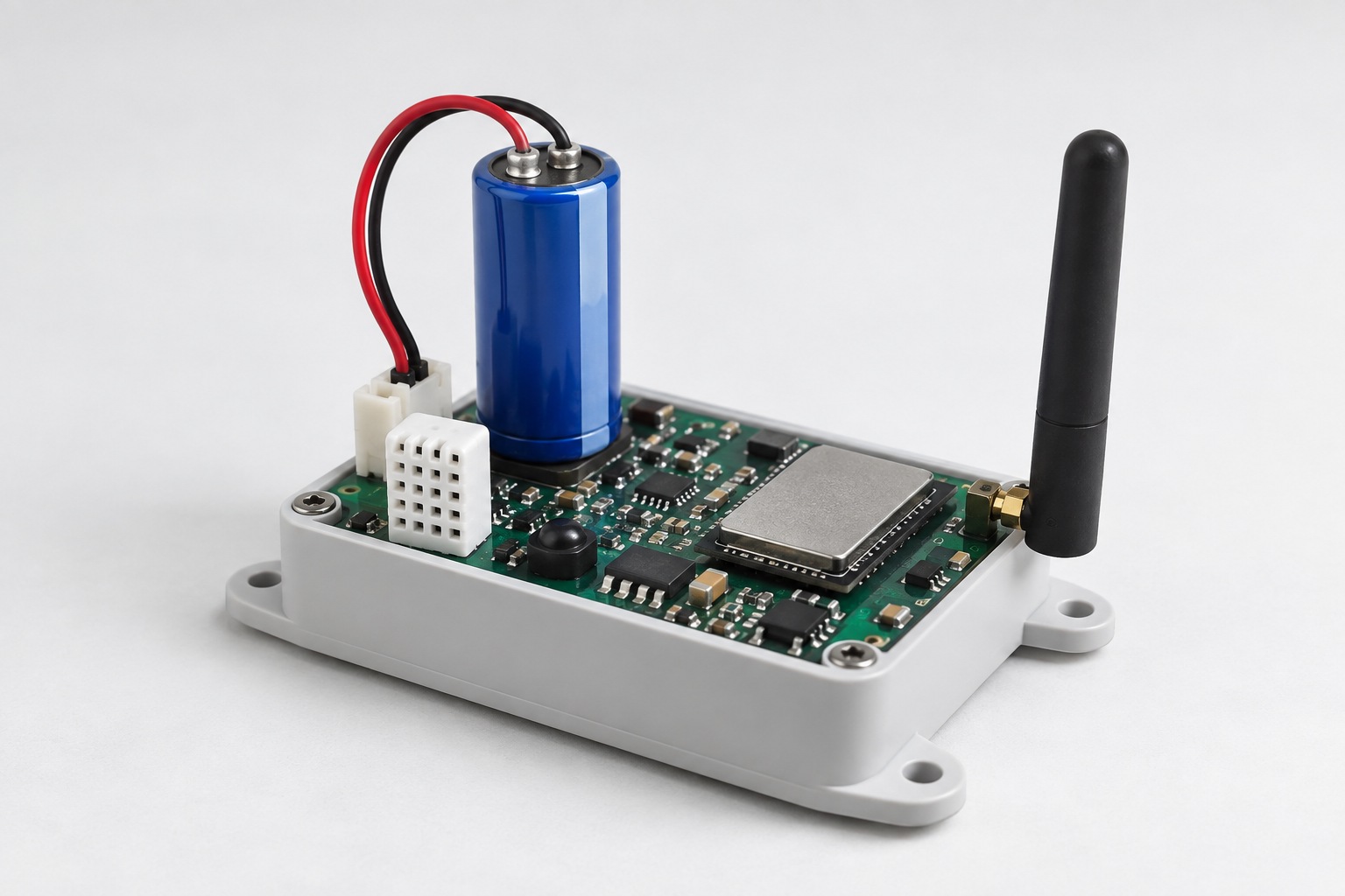 IoT NodesBuffer a sensor or wireless transmission duty cycle in an intermittent-power node.
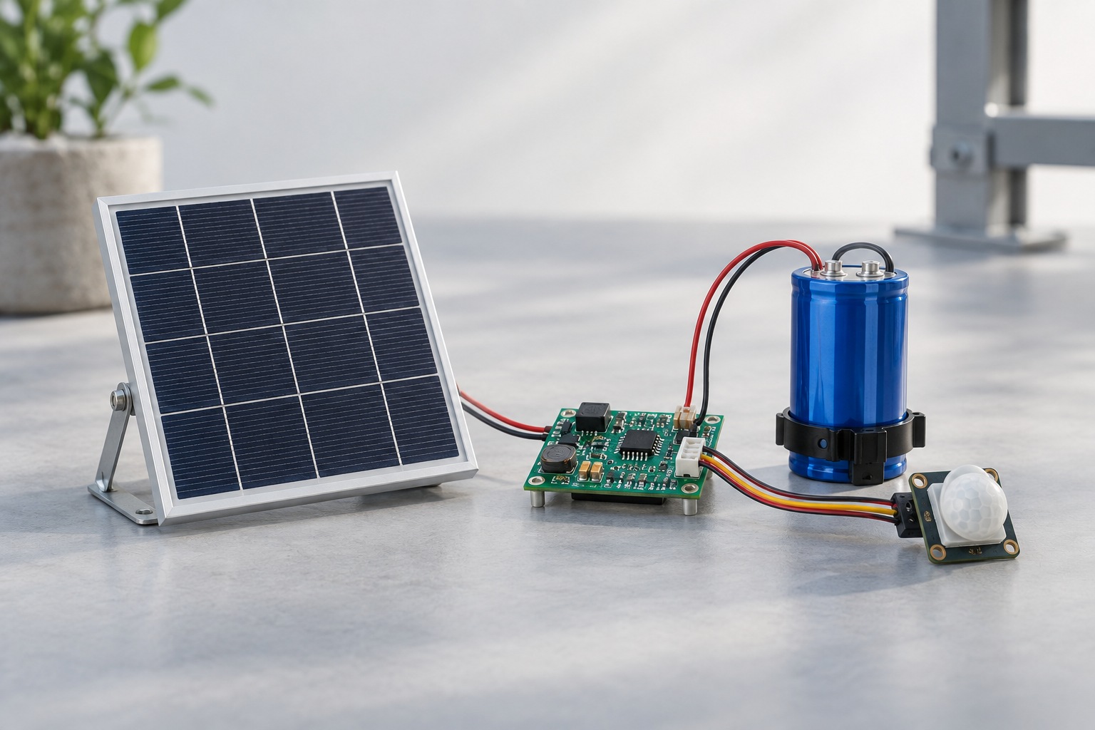 Energy HarvestingAccumulate small solar or transducer energy before enabling a low-power load.
| Application | Primary design check | Typical circuit support |
|---|---|---|
| Memory or RTC hold-up | Required retention current and minimum retention voltage | Controlled diode or load-switch isolation. |
| Controlled shutdown | Energy needed for processor save-and-power-down sequence | Power-fail signal and managed discharge path. |
| Sensor-node burst load | Radio pulse current, ESR sag and recharge time | Current-limited source and local decoupling. |
| Harvested-energy node | Leakage budget versus harvested current | Energy-harvesting controller with voltage window. |
13 · Engineering answers
NR2R7L105S-P0820 FAQs
What are the rated voltage and capacitance?
The supplied specification lists 2.7 V rated voltage and 1.0 F nominal capacitance, with a capacitance tolerance of -20% to +50%.
How much energy can it store?
The supplied PDF lists 0.0033 W·h maximum stored energy. Usable system energy is lower if the load has a minimum operating voltage; validate the result at the actual discharge cutoff.
What is the maximum ESR?
The PDF lists 95 mΩ maximum equivalent series resistance at 1 kHz. Include this, along with board and connector resistance, when estimating pulse voltage sag.
What are the body dimensions?
The nominal body is φ8.0 mm diameter × 20.0 mm length, with 0.6 mm leads on a 3.5 mm pitch.
Can I connect this supercapacitor in series?
Series use needs voltage balancing and a complete system review because individual capacitor voltages may not remain equal. Do not assume a simple series connection is safe without a balancing strategy.
Can I apply reverse voltage?
No. The component is polarized. Prevent reverse voltage in normal operation, test fixtures, battery replacement and fault conditions.
What operating temperature range is specified?
The specified operating range is -40 °C to +70 °C. Validate the complete product at the actual thermal extremes.
What should be checked during assembly?
Verify polarity, lead pitch, body clearance, soldering process, sleeve condition and mechanical stress. Do not bend or twist the capacitor body after installation.
This page summarizes the supplied NR2R7L105S-P0820 product specification for engineering evaluation. Confirm the current controlled specification, dimensions, polarity, electrical limits, reliability requirements and assembly process against the released datasheet before production release.
