RFID Reader IC Selection
How to Choose a 13.56 MHz RFID Reader IC
A practical engineering guide to protocols, host interfaces, low-power operation, antenna design, read range and migration risk.
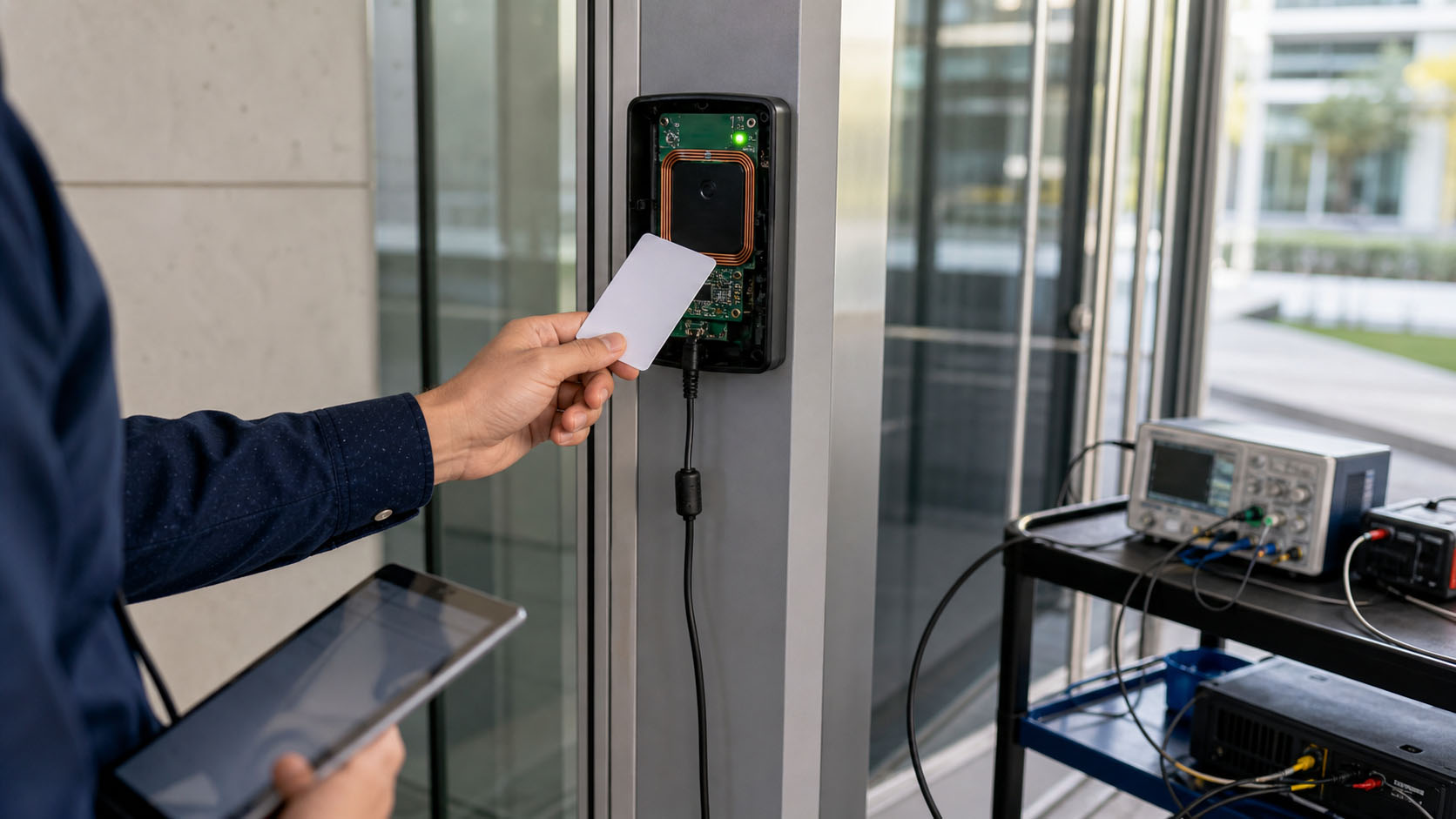
13.56 MHz RFID reader ICs are used in smart locks, access-control terminals, identification systems, equipment authentication, library systems and portable readers. Devices operating at the same frequency may still support different protocols, power modes and system architectures.
Choose the required card or tag protocol first. Then evaluate the host interface, power strategy, antenna and read-range requirements, electrical limits, software migration effort and supplier support. Do not select a reader IC solely by unit price or an advertised maximum read range.
Key takeaways
- Protocol compatibility comes first: Type A, Type B and ISO/IEC 15693 are not interchangeable.
- Read range is a complete-system result, not an IC-only specification.
- Battery-powered products need LPCD behavior and total system current to be evaluated together.
- A similar package does not guarantee pin, register or firmware compatibility.
- Reference designs and application support can reduce total engineering cost and time to production.
1. Start with the card or tag protocol
The target credential determines which reader functions are mandatory. Confirm the protocol from the card, tag or application specification before comparing IC features.
| Protocol | Typical applications | Selection consideration |
|---|---|---|
| ISO/IEC 14443 Type A | Smart locks, access cards, identification | Widely used for short-range proximity-card systems |
| ISO/IEC 14443 Type B | Identity, public-service and specialized cards | Required when the target credential uses Type B |
| ISO/IEC 15693 | Libraries, assets and industrial tags | Common for vicinity-tag and inventory applications |
A reader/writer IC is also different from a full NFC controller. If the product needs card emulation, peer-to-peer communication or a complete NFC software stack, verify those functions explicitly.
2. Select the host interface
| Interface | Strength | Design trade-off |
|---|---|---|
| SPI | High throughput and predictable timing | Uses more MCU pins |
| I²C | Two-wire bus and easy peripheral sharing | Lower throughput and address/bus-management considerations |
| UART | Simple point-to-point integration | Baud-rate and framing requirements must match |
The interface with the highest data rate is not automatically the best choice. Review MCU resources, PCB routing, interrupt behavior, driver availability and latency requirements.
3. Treat read range as a system-level result
Published read-range figures are useful only when the test conditions are understood. Actual performance depends on:
- Card or tag antenna size, resonance and sensitivity
- Reader antenna geometry, inductance, Q factor and matching network
- RF supply voltage, transmitter configuration and PCB layout
- Enclosure materials, nearby metal, cables and environmental detuning
- EMC limits and manufacturing tolerance
Do not treat values from separate data sheets as same-condition benchmark results. Measure performance with the production antenna, enclosure and representative tag set.
4. Evaluate low-power card detection
Battery-powered readers often spend most of their life waiting for a card. Check Hard Power-Down (HPD), Soft Power-Down (SPD) and Low-Power Card Detection (LPCD), together with wake time, detection interval and false-trigger behavior.
Total standby current also includes the MCU, clock source, regulator, pull-ups and other peripherals. An attractive IC-only current does not guarantee an equally low product-level result.
5. Check package, power and operating limits
- Package dimensions, exposed pad and PCB land pattern
- Digital, analog, I/O and RF-transmitter supply ranges
- Clock, reset, interrupt and auxiliary-pin requirements
- Operating temperature and ESD/EMC targets
- Lifecycle, traceability and production supply planning
Two reader ICs can look similar and still require PCB or firmware changes. Verify the pin map, electrical behavior and register-level dependencies before calling a part “drop-in compatible.”
6. Include software and support in total cost
The lowest component price does not always create the lowest product cost. Driver availability, schematic review, antenna-tuning guidance, low-power configuration, card-compatibility testing and production support can materially reduce engineering time and launch risk.
Quick selection guide by application
| Application | Priority | What to verify |
|---|---|---|
| Smart locks and portable readers | Low power | Type A, LPCD current, wake time and false detections |
| Access control and identification | Credential compatibility | Type A/B, ESD robustness and stable read performance |
| Library, asset and industrial systems | Tag protocol and antenna | ISO/IEC 15693, read-zone consistency and detuning |
| Multi-card platforms | Protocol coverage | Supported modes, data rates and firmware scalability |
| Existing MFRC522 designs | Migration effort | Package, pins, registers, interfaces, antenna and tag set |
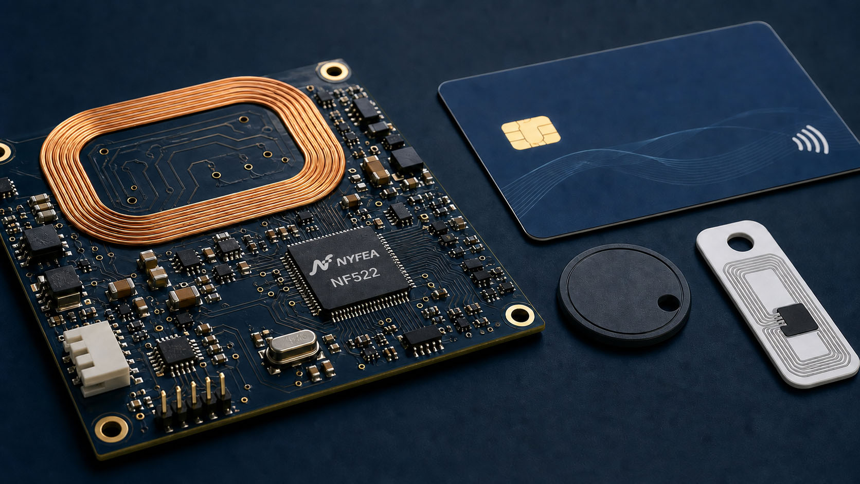
When is NYFEA NF522 a suitable option?
NF522 is designed for MFRC522-compatible migration and new multi-protocol 13.56 MHz reader products. Key functions include:
- ISO/IEC 14443 Type A, Type B and ISO/IEC 15693
- Type A/B data rates up to 848 kbit/s
- SPI, I²C and UART host interfaces; SPI up to 12 Mbit/s in modes 0 and 3
- 64-byte FIFO and 27.12 MHz external clock
- HPD, SPD and LPCD low-power modes
- QFN32 package and −25°C to +85°C operating range
NF522 technical data specifies typical LPCD current of 9.27 µA with AVDD and TVDD at 3.3 V and an external clock. With a suitable antenna, tag and matching network, reader distance can reach up to 100 mm. Both figures depend on stated test conditions and must be validated in the final product.
For an existing MFRC522 design, NF522 can provide a practical migration path. Confirm the production PCB, pin use, firmware functions, antenna matching and representative cards or tags before volume release.
Final selection checklist
- Identify every required card and tag protocol.
- Choose the host interface that fits the MCU and firmware architecture.
- Define read range in the final enclosure, not only on an open test board.
- Confirm the available antenna area and nearby materials.
- Measure LPCD behavior and total standby power where relevant.
- Verify package, voltages, temperature and protection requirements.
- Estimate PCB, driver and application-code migration work.
- Assess reference designs, engineering support and volume supply.
Frequently asked questions
Can all 13.56 MHz RFID reader ICs read the same cards?
No. Operating frequency alone does not define compatibility. The reader IC and target card or tag must support the same protocol and communication mode.
What is the difference between ISO/IEC 14443 and ISO/IEC 15693?
ISO/IEC 14443 is commonly used for proximity cards and identification systems. ISO/IEC 15693 is commonly used for vicinity tags, library systems and asset identification.
Which host interface is best?
There is no universal best interface. SPI favors throughput and deterministic timing, I²C reduces wiring, and UART can simplify some embedded designs.
How should a low-power RFID reader IC be selected?
Compare LPCD current, detection interval, wake time and false-trigger behavior, then measure total product current with the MCU, clock and power circuitry included.
Is read range determined mainly by the reader IC?
No. Antenna geometry, impedance matching, tag sensitivity, supply conditions, PCB layout, enclosure materials and nearby metal all affect the result.
Technical sources
- NYFEA NF522 product information
- NXP MFRC522 data sheet
- NYFEA NF522 technical data, internal product revision reviewed for this article.