
NTC0201 Series 0201-Size Chip NTC Thermistors
The NYFEA NTC0201 Series comprises two-terminal, surface-mount negative-temperature-coefficient thermistors in the 0201 imperial (0603 metric) size. Available nominal zero-power resistance at 25 °C (R25) values are 10 kΩ, 47 kΩ, 68 kΩ, and 100 kΩ, with R25 tolerances of ±1%, ±3%, or ±5% and part-specific B-constant characteristics.
Product scope: NTC0201 is a passive resistive sensing element, not a digital temperature-sensor IC or a self-contained protection device. The external circuit must provide controlled excitation, analog measurement, resistance-to-temperature conversion, calibration as required, suitable thermal coupling, and application-level fault handling.
Use the applicable product specification for part-number selection, procurement, incoming inspection, PCB release, reflow-profile approval, and production qualification.
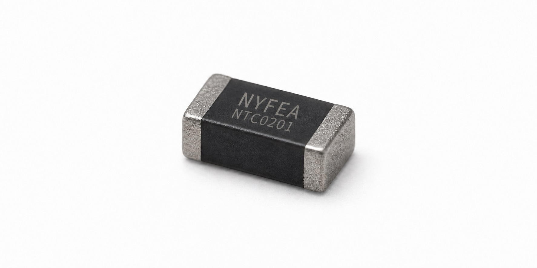
NTC0201 Product Overview and Scope
NTC0201 provides a predictable decrease in resistance as temperature rises. Its miniature 0201 package is suited to temperature-sensing locations with limited PCB area. At this scale, however, pad geometry, solder volume, mechanical stress, excitation power, nearby heat sources, and PCB heat flow can materially affect the measured temperature.
| Selection question | NTC0201 specification | System-level decision |
|---|---|---|
| What component category is it? | Passive, two-terminal chip NTC thermistor. | Provide analog excitation and resistance-to-temperature conversion externally. |
| Which nominal R25 values are listed? | 10 kΩ, 47 kΩ, 68 kΩ, and 100 kΩ at 25 °C. | Select the value to suit the ADC input range, required resolution, excitation current, allowable self-heating, leakage, and temperature span. |
| Which R25 tolerances are available? | F: ±1%; H: ±3%; J: ±5%. | Include R25 tolerance, B-constant behavior, ADC and reference errors, thermal offsets, and calibration residuals in the complete error budget. |
| What is the rated power? | 100 mW at 25 °C. | This is a specified rating, not a recommended measurement power. Use substantially lower excitation when temperature accuracy matters. |
| What is the operating temperature range? | −40 °C to +125 °C ambient. | Verify performance over the actual mounting condition, dwell time, environment, and product mission profile. |
Ordering Codes and Part-Number Selection
Selection Highlights
- Miniature SMD format: 0201 imperial (0603 metric), measuring 0.60 ±0.05 mm × 0.30 ±0.05 mm × 0.30 ±0.05 mm.
- Specified R25 choices: 10 kΩ, 47 kΩ, 68 kΩ, and 100 kΩ.
- Resistance-tolerance grades: ±1%, ±3%, and ±5%.
- Thermal time constant: less than 3 s under the product-specification method, which measures the 63.2% temperature change after excitation is switched from non-zero power to zero power; this is not a guaranteed finished-system response time.
- Dissipation factor: 1.0 mW/°C under the specified condition; mounted behavior depends on the PCB and surrounding thermal paths.
- Tape-and-reel packing: paper carrier tape, 15,000 units per reel.
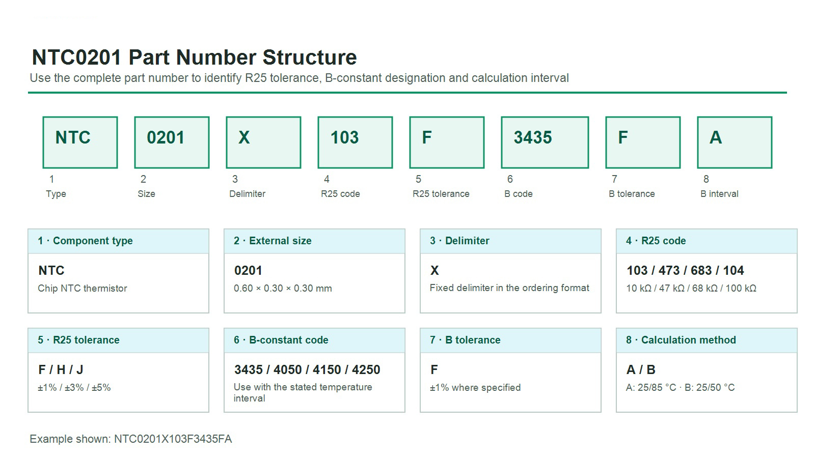
How to Read the Listed Part Numbers
| Field | Meaning | Values relevant to the listed NTC0201 range |
|---|---|---|
| NTC | Component category | Chip NTC thermistor |
| 0201 | External size code | 0.60 × 0.30 × 0.30 mm |
| X | Delimiter | Fixed delimiter shown in the ordering format |
| 103 / 473 / 683 / 104 | Nominal resistance code at 25 °C | 10 kΩ / 47 kΩ / 68 kΩ / 100 kΩ |
| F / H / J | R25 tolerance | ±1% / ±3% / ±5% |
| 3435 / 4050 / 4150 / 4250 | B-constant code | Use with the calculation interval identified by the final A or B character |
| F | B-constant tolerance code | ±1% for the B value explicitly identified with a tolerance in the electrical table |
| A / B | B calculation temperatures | A: 25 °C and 85 °C; B: 25 °C and 50 °C |
Part Numbers Listed in the Product Specification
The product specification lists the following twelve combinations. The B-constant data and permissible current are the same across the F, H, and J R25-tolerance grades within each resistance family.
| Listed part number | Nominal R25 and tolerance | B25/50 | B25/85 | Permissible current at 25 °C |
|---|---|---|---|---|
| NTC0201X103F3435FA | 10 kΩ ±1% | 3380 K | 3435 K ±1% | 0.31 mA |
| NTC0201X103H3435FA | 10 kΩ ±3% | 3380 K | 3435 K ±1% | 0.31 mA |
| NTC0201X103J3435FA | 10 kΩ ±5% | 3380 K | 3435 K ±1% | 0.31 mA |
| NTC0201X473F4050FB | 47 kΩ ±1% | 4050 K ±1% | 4100 K | 0.14 mA |
| NTC0201X473H4050FB | 47 kΩ ±3% | 4050 K ±1% | 4100 K | 0.14 mA |
| NTC0201X473J4050FB | 47 kΩ ±5% | 4050 K ±1% | 4100 K | 0.14 mA |
| NTC0201X683F4150FB | 68 kΩ ±1% | 4150 K ±1% | 4210 K | 0.12 mA |
| NTC0201X683H4150FB | 68 kΩ ±3% | 4150 K ±1% | 4210 K | 0.12 mA |
| NTC0201X683J4150FB | 68 kΩ ±5% | 4150 K ±1% | 4210 K | 0.12 mA |
| NTC0201X104F4250FB | 100 kΩ ±1% | 4250 K ±1% | 4310 K | 0.10 mA |
| NTC0201X104H4250FB | 100 kΩ ±3% | 4250 K ±1% | 4310 K | 0.10 mA |
| NTC0201X104J4250FB | 100 kΩ ±5% | 4250 K ±1% | 4310 K | 0.10 mA |
The absence of a tolerance next to 3380 K, 4100 K, 4210 K, or 4310 K is retained from the product specification. Do not infer or assign an unstated tolerance to those reference values.
NTC Principle, B-Constant Method, and R–T Approximation
NTC0201 has no digital communications interface; its electrical output is resistance. A measurement circuit applies controlled excitation, measures the resulting voltage or current, and converts the calculated resistance to temperature using the R25 and B data for the exact part number or a validated resistance-temperature lookup table.
Analog resistance
Two terminals; polarity independent for ordinary resistance measurement.
R25 at 25 °C
Nominal zero-power resistance is specified at 25 °C.
B constant
The applicable B value depends on whether it is calculated across 25/50 °C or 25/85 °C.
Host responsibility
ADC conversion, linearization, calibration, diagnostics, and fault response are external.
For preliminary calculations, the B-parameter equation is commonly written as R(T) = R25 × exp[B × (1/T − 1/T25)]. Here, R(T) is resistance at absolute temperature T, R25 is nominal zero-power resistance at 25 °C, T and T25 are in kelvin, and T25 = 298.15 K. This is an engineering approximation over the interval associated with the stated B constant. Do not substitute B25/50 for B25/85 or assume that one B value defines the full −40 °C to +125 °C curve.
Measurement Circuit, ADC Readout, and Fault Detection
As a passive two-terminal device, NTC0201 does not contain an interface circuit. The designer must select an excitation and readout topology to suit the temperature range, required resolution, ADC reference, allowable self-heating, fault-detection strategy, and power budget.
Excitation Power, Self-Heating, and Measurement Error
NTC0201 has no supply current or sleep state. Its electrical power is set entirely by the external excitation. Treat self-heating both as a power-budget item and as a potential temperature-measurement offset.
| Nominal R25 | Permissible operating current at 25 °C | Calculated I²R at nominal R25 | Datasheet definition |
|---|---|---|---|
| 10 kΩ | 0.31 mA | 0.96 mW | Current is defined as producing a 1 °C body-temperature rise on the PCB in still air. |
| 47 kΩ | 0.14 mA | 0.92 mW | Same 25 °C, still-air, PCB-mounted definition. |
| 68 kΩ | 0.12 mA | 0.98 mW | Same 25 °C, still-air, PCB-mounted definition. |
| 100 kΩ | 0.10 mA | 1.00 mW | Same 25 °C, still-air, PCB-mounted definition. |
The I²R values are rounded calculations from the listed nominal R25 and permissible-current values; they are not additional guaranteed parameters. The specification lists a dissipation factor of 1.0 mW/°C. For precision sensing, use lower continuous current or duty-cycled excitation and validate self-heating on the actual PCB, in the final enclosure and airflow condition.
Zero-Power Measurement Reference
The R25 test method specifies an ambient temperature of 25 ±0.05 °C and measurement power of ≤0.1 mW. This is a characterization condition, not an automatic guarantee for a production ADC circuit. Calculate worst-case excitation power across the relevant resistance, supply, and component tolerances.
Electrical Characteristics, Test Conditions, and Dimensions
Specification Test and Measurement Conditions
| Measurement or test | Condition stated in the product specification | Engineering interpretation |
|---|---|---|
| Standard atmospheric conditions | 20 ±15 °C; 65 ±20% RH; 86 kPa to 106 kPa | Applicable unless another condition is specified for the individual test. |
| Reference conditions if results are in doubt | 25 ±2 °C; 65 ±5% RH; 86 kPa to 106 kPa | Use these tighter environmental limits when resolving a disputed test result. |
| Nominal zero-power resistance R25 | 25 ±0.05 °C; measuring power ≤0.1 mW | Characterization condition for R25; it is not a recommended production-circuit excitation level. |
| Nominal B constant | Resistance measured at 25 ±0.05 °C and at 50 ±0.05 °C or 85 ±0.05 °C | Use absolute temperature in kelvin and the interval identified by the exact part number. |
Listed Electrical Characteristics
| Nominal R25 | F / H / J part-number families | B25/50 | B25/85 | Permissible current at 25 °C |
|---|---|---|---|---|
| 10 kΩ | NTC0201X103[F/H/J]3435FA | 3380 K | 3435 K ±1% | 0.31 mA |
| 47 kΩ | NTC0201X473[F/H/J]4050FB | 4050 K ±1% | 4100 K | 0.14 mA |
| 68 kΩ | NTC0201X683[F/H/J]4150FB | 4150 K ±1% | 4210 K | 0.12 mA |
| 100 kΩ | NTC0201X104[F/H/J]4250FB | 4250 K ±1% | 4310 K | 0.10 mA |
Square brackets are shorthand for the three orderable R25-tolerance variants: F = ±1%, H = ±3%, and J = ±5%. They are not part of the orderable part number. B values and tolerance placement are reproduced from the product specification; do not assign an unstated tolerance to the adjacent reference value.
| Parameter | Specified value | Condition or interpretation |
|---|---|---|
| Dissipation factor | 1.0 mW/°C | Power required to raise body temperature by 1 °C under the defined condition. |
| Thermal time constant | <3 s | Time to complete 63.2% of the temperature change after excitation switches from non-zero power to zero power under the specified method; not a guaranteed finished-system response time. |
| Rated power | 100 mW at 25 °C | Power associated with a 100 °C self-heating rise at 25 °C in the specification definition. |
| Operating ambient | −40 °C to +125 °C | Do not operate beyond this specified range. |
| Body length L | 0.60 ±0.05 mm | 0.024 ±0.002 in |
| Body width W | 0.30 ±0.05 mm | 0.012 ±0.002 in |
| Body thickness T | 0.30 ±0.05 mm | 0.012 ±0.002 in |
| Terminal dimension a | 0.15 ±0.05 mm | 0.006 ±0.002 in |
| Recommended land A | 0.20 to 0.30 mm | Dimension A in the controlled land-pattern drawing. |
| Recommended land B / C | 0.25 to 0.35 mm / 0.25 to 0.35 mm | Dimensions B and C in the controlled drawing; validate the complete assembly process. |
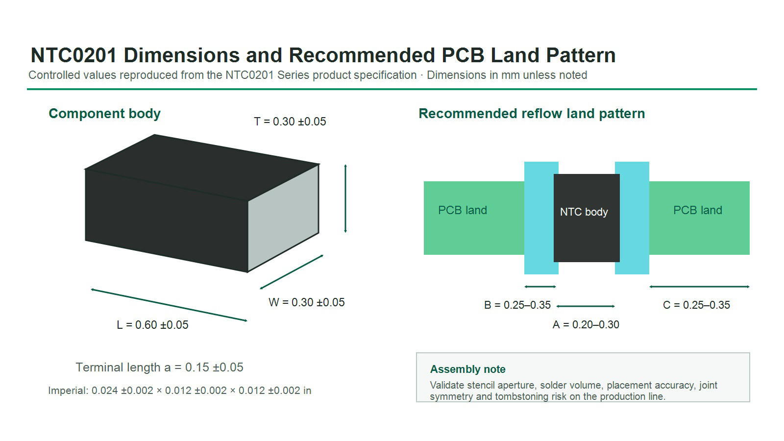
PCB Land Pattern, Soldering, Reliability, Packing, and Storage
Reflow Soldering Window
- Ramp: 1 to 2 °C/s.
- Preheat: 150 to 170 °C for 90 ±30 s.
- Time above 240 °C: 20 to 40 s.
- Peak: 260 °C maximum for 10 s.
- Maximum number of reflow cycles: two.
- Specified solder alloy: 96.5Sn / 3.0Ag / 0.5Cu.
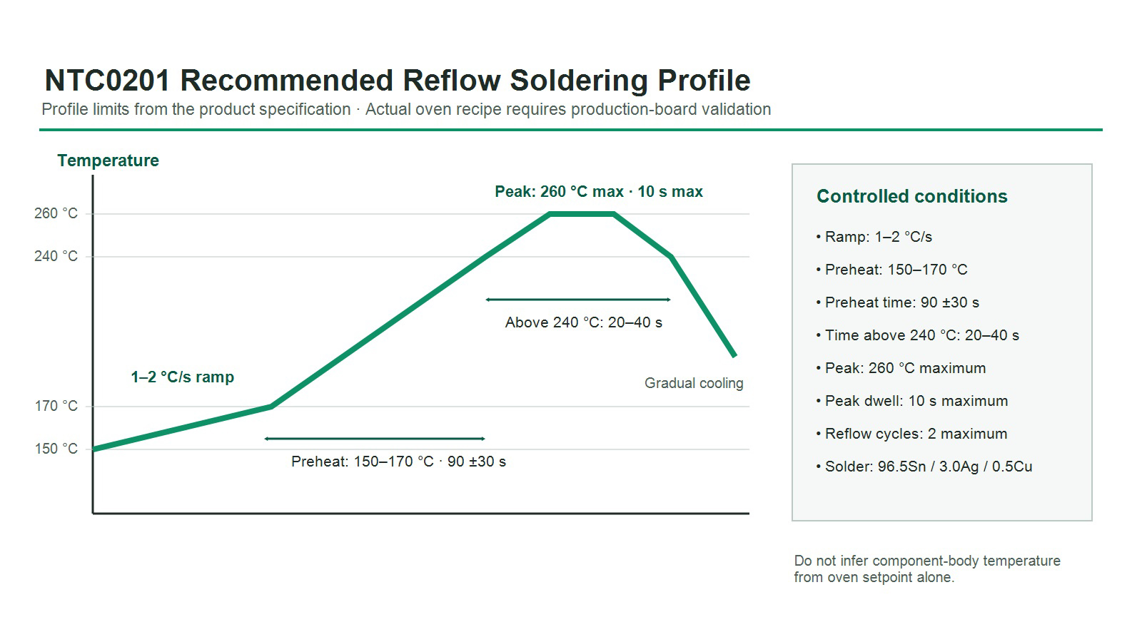
Manual Soldering Boundary
For manual soldering, the specification limits the soldering iron to 20 W maximum, requires preheating at 150 °C for 60 s, limits tip temperature to 280 °C and contact time to 3 s, and permits one manual-soldering operation. The specified solder alloy is 96.5Sn / 3.0Ag / 0.5Cu. Do not touch the terminal electrodes with the iron tip.
Reliability Test Conditions
| Test | Condition | Requirement shown in the specification |
|---|---|---|
| Terminal strength | 2 N for 10 ±1 s | No terminal removal, ceramic split, or other defect. |
| Board flexure | 1 mm, <0.5 mm/s, 10 ±1 s | No visible damage; |ΔR25/R25| ≤2%. |
| Vibration | 10 to 55 Hz, 1.5 mm total amplitude, 2 h in each of three axes | No visible damage. |
| Drop | 1 m onto concrete, 10 times | No visible damage. |
| Solderability | 245 ±5 °C for 3 ±0.3 s | At least 95% wetting coverage. |
| Soldering heat | 260 ±5 °C for 10 ±1 s | No visible damage; |ΔR25/R25| ≤2%; |ΔB/B| ≤1%. |
| Temperature cycling | Five cycles: −40 ±5 °C for 30 ±3 min; 25 ±2 °C for 5 ±3 min; 125 ±2 °C for 30 ±3 min; 25 ±2 °C for 5 ±3 min | No visible damage; |ΔR25/R25| ≤2%; |ΔB/B| ≤1%. |
| Dry heat / cold storage | 125 ±5 °C for 1000 ±24 h / −40 ±3 °C for 1000 ±24 h | No visible damage; |ΔR25/R25| ≤2%; |ΔB/B| ≤1%. |
| Damp heat | 40 ±2 °C, 90% to 95% RH, 1000 ±24 h | No visible damage; |ΔR25/R25| ≤2%; |ΔB/B| ≤1%. |
| High-temperature load | 85 ±2 °C, permissible operating current, 1000 ±48 h | No visible damage; |ΔR25/R25| ≤2%; |ΔB/B| ≤1%. |
For resistance-to-soldering-heat and environmental endurance tests, the specification requires stabilization for 1 to 2 hours under normal conditions before measurement.
Packing and Storage
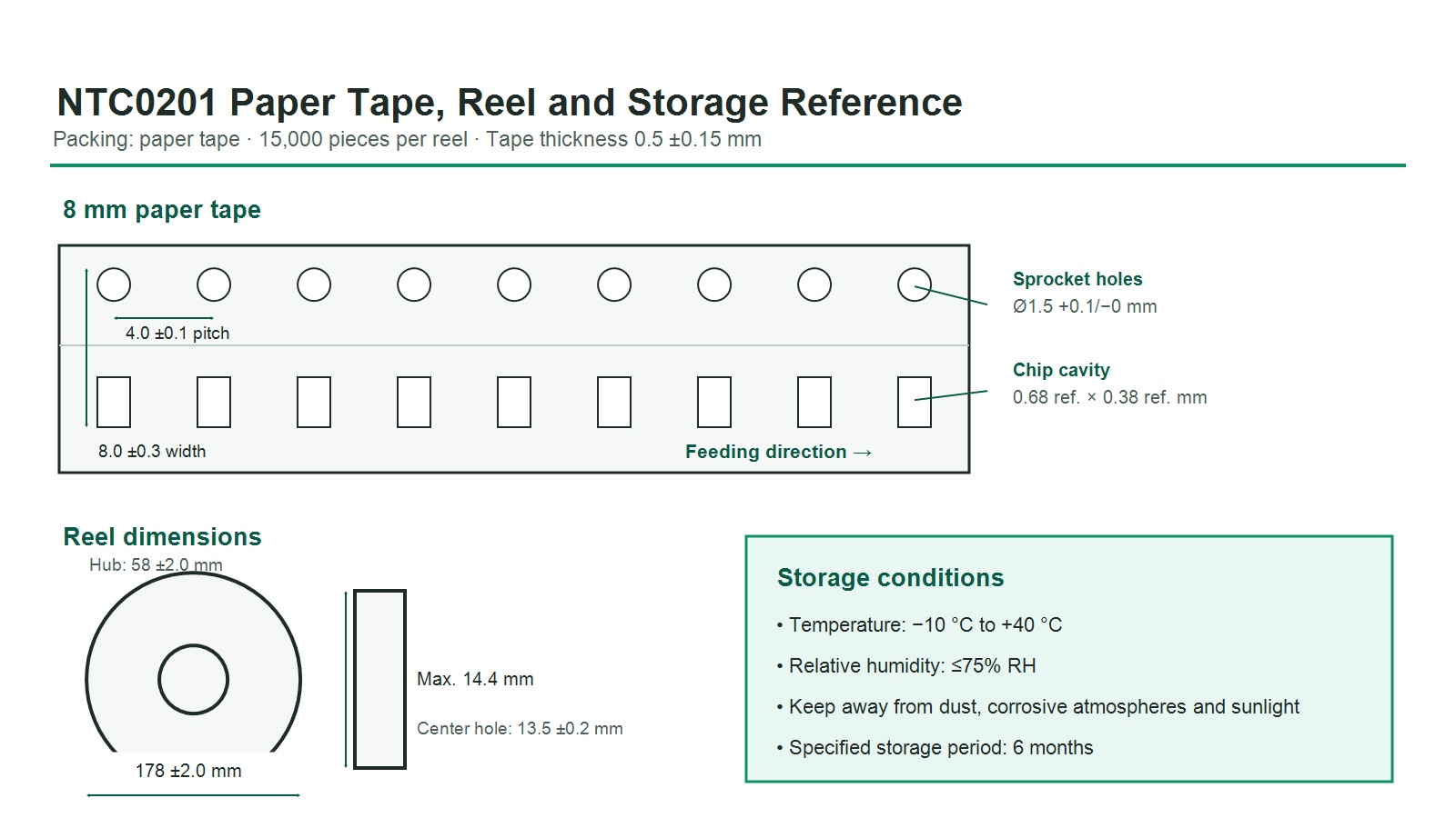
NTC0201 is supplied on paper carrier tape, 15,000 units per reel. Tape thickness is 0.5 ±0.15 mm. Store at −10 °C to +40 °C and no more than 75% RH, protected from dust, corrosive atmospheres, and direct sunlight. The product specification states a storage period of six months; confirm the lot date and storage history before use.
Application Guidance and Design Limitations
The product specification does not grant application-specific approval. The following are potential use categories that require circuit, thermal, mechanical, environmental, assembly, and safety qualification in the final product.
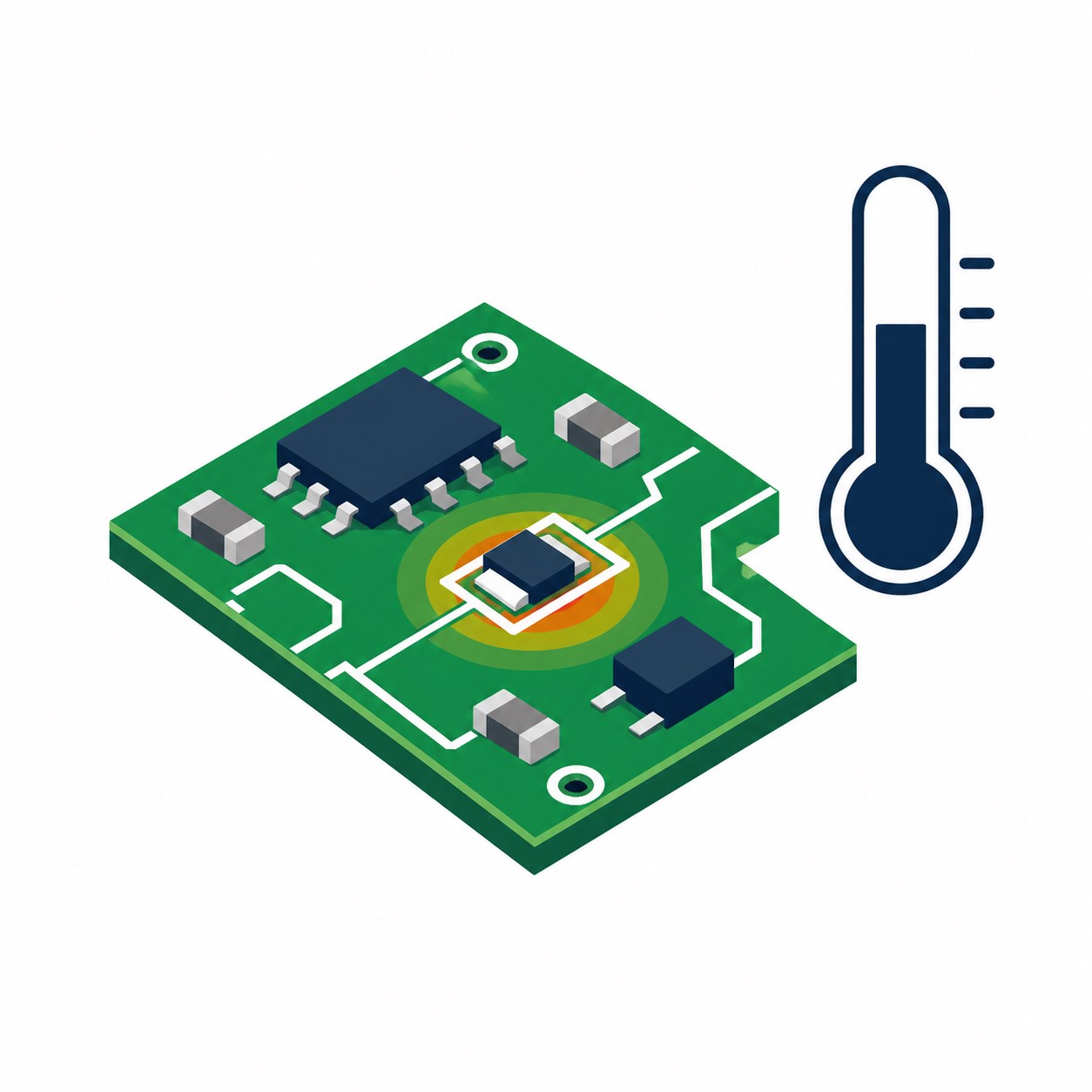 Compact PCB temperature sensingSuitable where PCB area and sensor thermal mass must be minimized. Validate offsets from nearby heat sources and copper heat spreading.
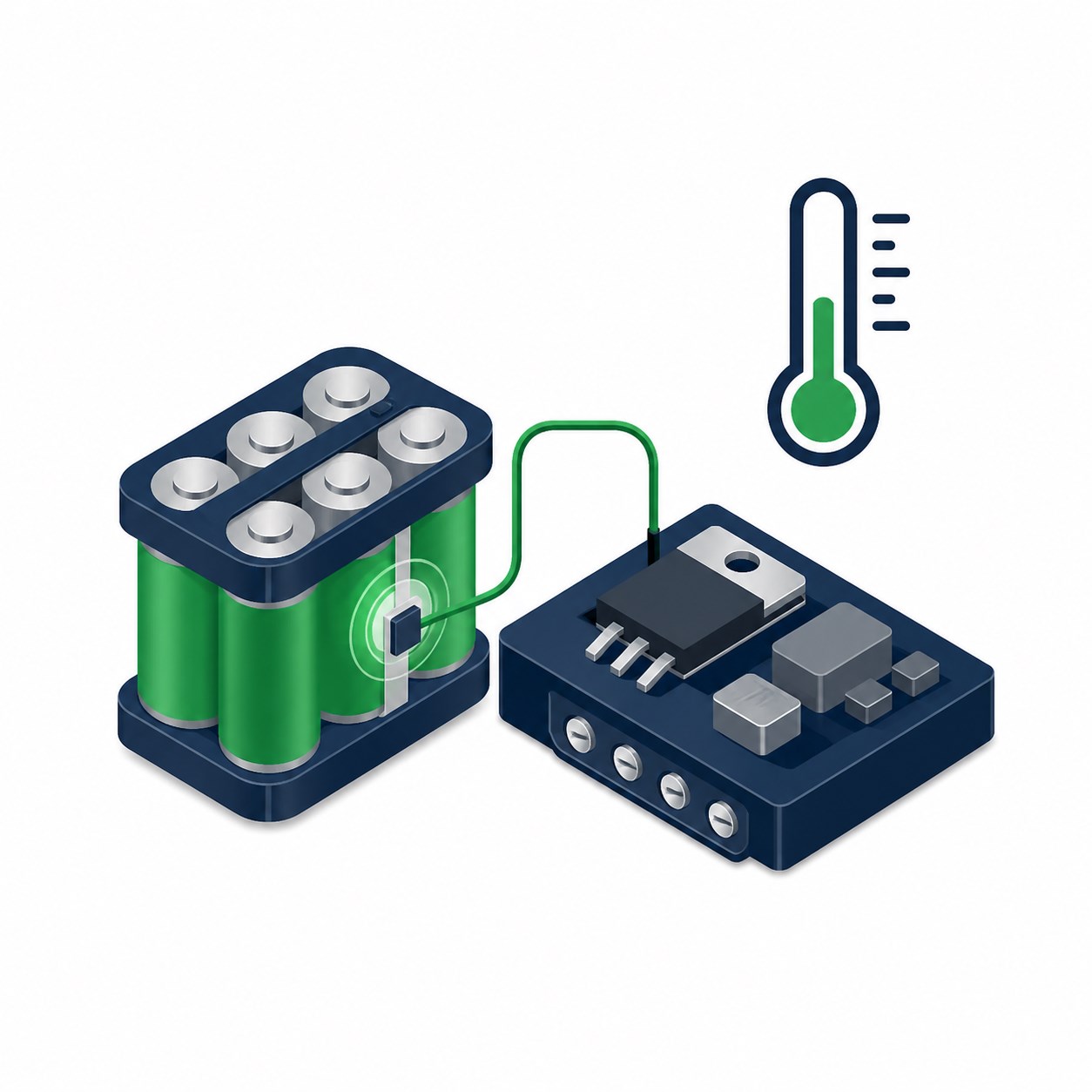 Battery and power-electronics monitoringUse with a defined thermal interface and appropriate system diagnostics. The thermistor alone does not provide a safety cutoff.
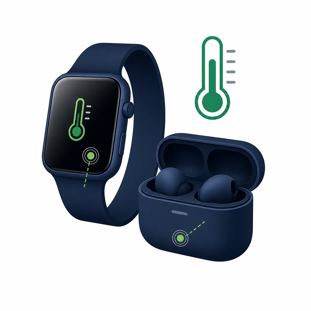 Wearable and portable electronicsThe miniature package supports dense designs, but handling, moisture protection, board flex, and excitation duty cycle require product-level validation.
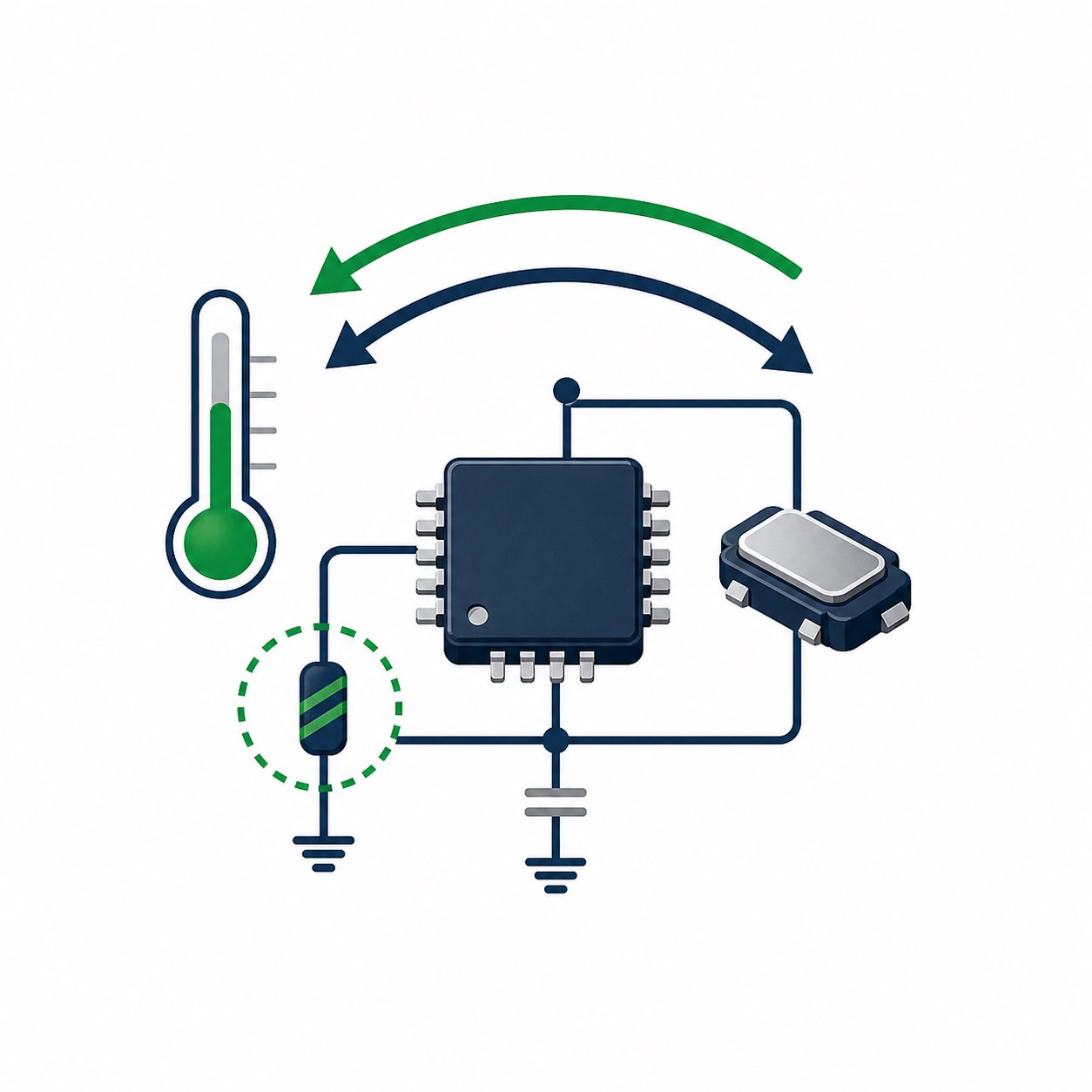 Temperature compensationProvides an analog temperature-dependent resistance for compensation algorithms when the selected R25, B model, placement, and calibration satisfy the error budget.
NTC0201 Engineering FAQs
What is the NTC0201 Series?
NTC0201 is a two-terminal surface-mount NTC thermistor series in a 0.60 × 0.30 × 0.30 mm body. Resistance decreases as temperature increases. As a passive sensing component, it requires an external analog measurement circuit.
What does “0201” mean in NTC0201?
In this product specification, 0201 is the imperial package designation for a nominal 0.60 × 0.30 × 0.30 mm body, commonly described as 0603 metric. Always verify the controlled dimensions because imperial and metric package naming can otherwise be confused.
Is NTC0201 a digital temperature sensor?
No. NTC0201 has no supply pin, digital address, communications protocol, register map, calibration memory, or digital output. The external circuit must measure resistance and convert it to temperature.
Which NTC0201 resistance values are listed?
The specification lists nominal R25 values of 10 kΩ, 47 kΩ, 68 kΩ, and 100 kΩ, each with ±1%, ±3%, or ±5% resistance-tolerance part-number families.
Which B constant should be used?
Use the B constant and calculation interval specified for the exact part number. The 10 kΩ family uses 3435 K for B25/85. The listed 47 kΩ, 68 kΩ, and 100 kΩ families use 4050 K, 4150 K, and 4250 K respectively for B25/50. Do not interchange B25/50 and B25/85 without a validated resistance-temperature model.
How much measurement current can be applied?
The specification lists permissible operating current at 25 °C from 0.31 mA for the 10 kΩ version to 0.10 mA for the 100 kΩ version. The value is defined by a 1 °C self-heating rise for a PCB-mounted component in still air. It is not a universal recommended measurement current. Precision designs normally use lower or duty-cycled excitation and verify self-heating in the final assembly.
What is the NTC0201 thermal time constant?
The listed thermal time constant is less than 3 s under the product-specification method, which measures the 63.2% temperature change after excitation switches from non-zero power to zero power. Response time in a finished product depends on PCB copper, solder joints, coating, airflow, enclosure, adhesive, contact pressure, and the temperature source.
Can the 100 mW rated power be used as measurement power?
No. Rated power is not a recommended measurement level. The specification defines 100 mW at 25 °C as the power associated with a 100 °C self-heating rise. A temperature-measurement circuit should operate far below that level and satisfy its allowable self-heating error.
What PCB land pattern is recommended?
The specification shows A = 0.20 to 0.30 mm, B = 0.25 to 0.35 mm, and C = 0.25 to 0.35 mm. Use the controlled drawing, then validate paste aperture, placement accuracy, solder volume, joint symmetry, tombstoning risk, and inspection criteria on the production assembly line.
Can NTC0201 replace any 10 kΩ 0201 thermistor?
Not automatically. Match the nominal R25, R25 tolerance, B-constant value and calculation interval, resistance-temperature curve, power and current limits, operating range, package dimensions, land pattern, assembly process, and qualification requirements before approving a substitution.
What reflow profile is specified?
The specified profile uses a 1 to 2 °C/s ramp, 150 to 170 °C preheat for 90 ±30 s, 20 to 40 s above 240 °C, and a 260 °C maximum peak for 10 s, with no more than two reflow cycles. The solder alloy shown is 96.5Sn/3.0Ag/0.5Cu.
Can NTC0201 provide overtemperature protection by itself?
No. NTC0201 provides only a temperature-dependent resistance. A protection function requires excitation, measurement, threshold logic, diagnostics, fault handling, and a suitable power-disconnect element designed to the required safety level.
How should NTC0201 be stored?
Store at −10 °C to +40 °C and ≤75% RH, away from dust, corrosive atmospheres, and sunlight. The product specification lists a six-month storage period.
This page summarizes the NYFEA NTC0201 Series product specification for component selection and engineering evaluation. It does not replace the complete product specification. Before production release, confirm the applicable revision, exact part number, R25 and B data, measurement conditions, land pattern, soldering profile, reliability requirements, packing, storage, and application qualification.
Download NTC0201 Product Specification Contact NYFEA for Product Support