
FHT41 Temperature & Humidity Sensor
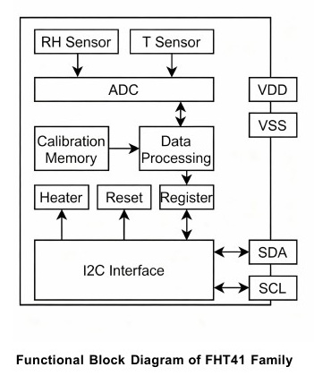
NYFEA FHT41 integrates calibrated relative-humidity and temperature sensing, three repeatability modes, CRC-protected I²C data, a unique serial number and an on-chip heater in a 1.5 mm × 1.5 mm DFN4 package.
Product scope: the supplied datasheet specifies typical ±1.8 %RH and ±0.2 °C accuracy, a 0 to 100 %RH range, -40 °C to +125 °C operation, and 1.6 V to 5.5 V supply. The FHT41-TR ordering entry specifies a 7-bit I²C address of 0x45.
This engineering selection page summarizes the supplied datasheet. Use the controlled specification for final limits, timing, address configuration, assembly and production release.
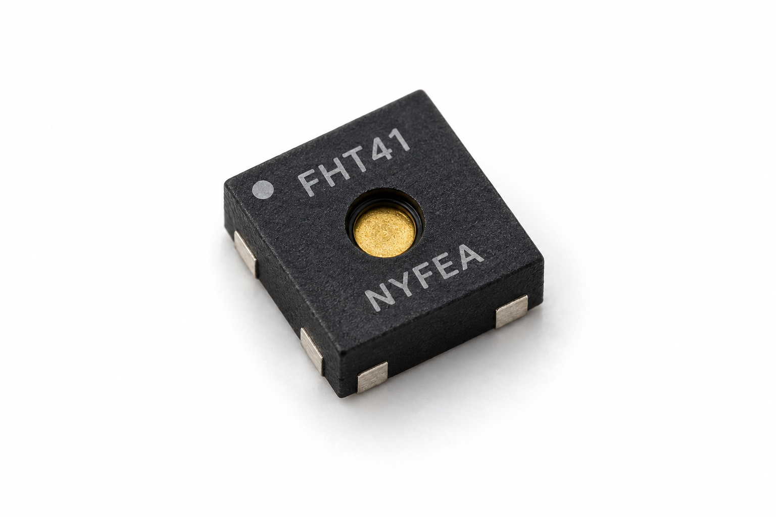
Product Overview and Selection Scope
FHT41 is a high-precision digital temperature and humidity sensor for low-power systems. Its compact package, selectable repeatability and integrated heater support space-constrained consumer, cabin and industrial designs.
- Humidity: 0 to 100 %RH, typical ±1.8 %RH accuracy.
- Temperature: -40 °C to +125 °C, typical ±0.2 °C accuracy.
- Repeatability: high, medium and low modes trade repeatability against conversion time and average current.
- Low current: 0.1 µA typical idle current and 0.4 µA typical at one low-repeatability measurement per second.
- I²C output: Standard, Fast and Fast Mode Plus operation up to 1 MHz.
- Data integrity: CRC-8 follows each 16-bit temperature, humidity or serial-number word.
- Integrated heater: three typical power settings and two pulse durations.
- Traceability: the source states NIST traceability and qualification to JEDEC JESD47.
Humidity and Temperature Performance
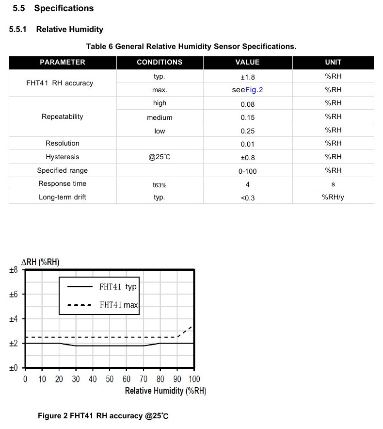
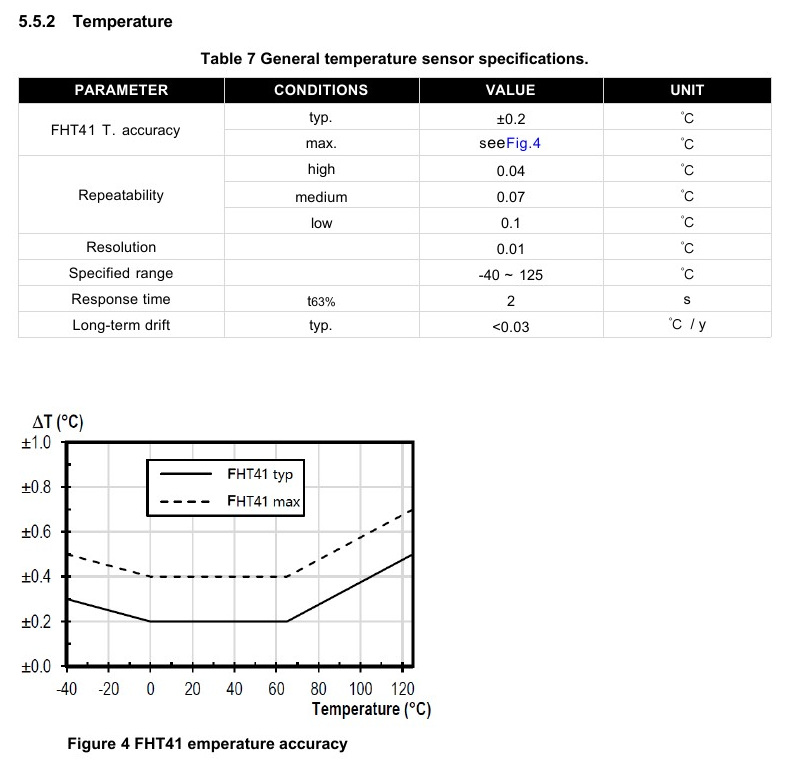
| Parameter | Humidity | Temperature | Condition / note |
|---|---|---|---|
| Typical accuracy | ±1.8 %RH | ±0.2 °C | See source curves for variation across range. |
| High repeatability | 0.08 %RH | 0.04 °C | Longest measurement duration. |
| Medium repeatability | 0.15 %RH | 0.07 °C | Intermediate time and current. |
| Low repeatability | 0.25 %RH | 0.1 °C | Lowest average current. |
| Resolution | 0.01 %RH | 0.01 °C | Digital output resolution. |
| Hysteresis | ±0.8 %RH | - | Humidity value at 25 °C. |
| Specified range | 0 to 100 %RH | -40 °C to +125 °C | Operating measurement range. |
| Response time, t63% | 4 s | 2 s | Sensor response entry. |
| Long-term drift, typical | <0.3 %RH/year | <0.03 °C/year | Typical values. |
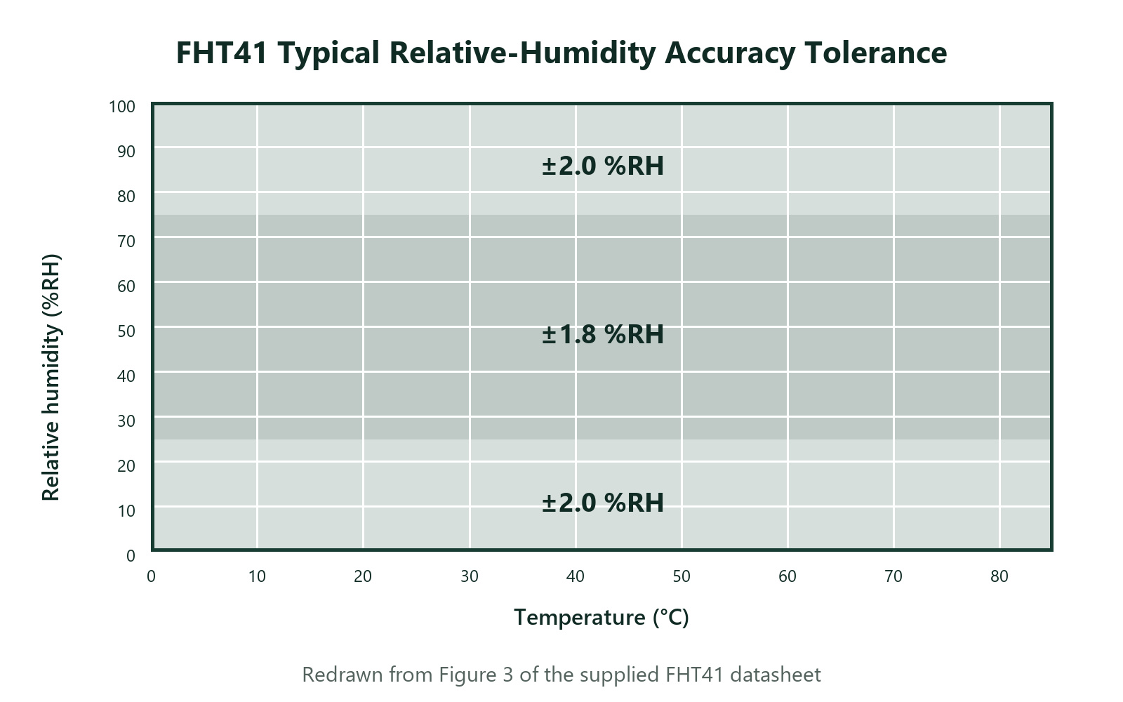
Electrical Characteristics and Timing
Unless otherwise stated, the source characterizes the device from -40 °C to +125 °C and VDD = 1.6 V to 5.5 V; typical values apply at 25 °C and 3.3 V.
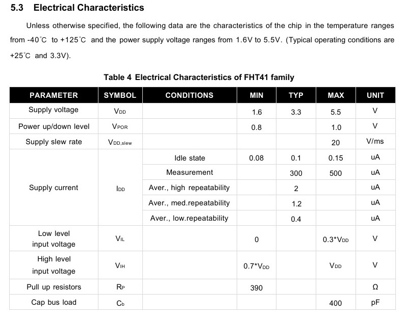
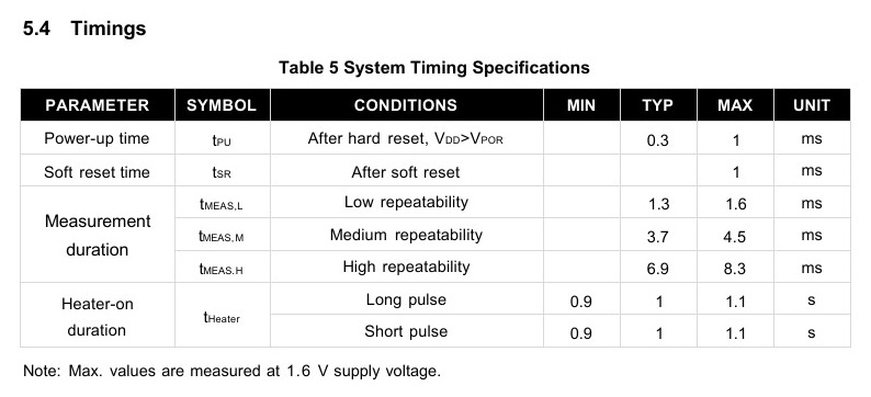
| Parameter | Minimum | Typical | Maximum | Unit / condition |
|---|---|---|---|---|
| Supply voltage, VDD | 1.6 | 3.3 | 5.5 | V |
| Power-up/down level, VPOR | 0.8 | - | 1.0 | V |
| Supply slew rate | - | - | 20 | V/ms |
| Idle current | 0.08 | 0.1 | 0.15 | µA |
| Measurement current | - | 300 | 500 | µA |
| Average current, high repeatability | - | 2 | - | µA at 1 Hz |
| Average current, medium repeatability | - | 1.2 | - | µA at 1 Hz |
| Average current, low repeatability | - | 0.4 | - | µA at 1 Hz |
| Input LOW, VIL | 0 | - | 0.3 × VDD | V |
| Input HIGH, VIH | 0.7 × VDD | - | VDD | V |
| Pull-up resistance, RP | 390 | - | - | Ω, source-table minimum |
| Bus capacitance, Cb | - | - | 400 | pF |
Measurement timing
| Operation | Typical | Maximum | Unit |
|---|---|---|---|
| Power-up after hard reset | 0.3 | 1 | ms |
| Soft reset | - | 1 | ms |
| Low-repeatability measurement | 1.3 | 1.6 | ms |
| Medium-repeatability measurement | 3.7 | 4.5 | ms |
| High-repeatability measurement | 6.9 | 8.3 | ms |
Absolute limits and source anomaly
The family absolute-maximum table lists -40 °C to +125 °C operating conditions, -40 °C to +150 °C storage, +150 °C maximum junction temperature, ±7 kV HBM ESD and ±200 mA latch-up. It also lists an “ALERT pin” limit of -0.5 V to +6 V, although the FHT41 pin table contains no ALERT pin. Confirm the applicable pin-stress limits in the controlled device specification.
Pin Assignment and Application Circuit
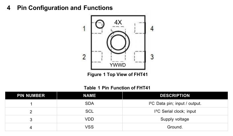
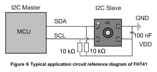
| Pin | Name | Function | Design guidance |
|---|---|---|---|
| 1 | SDA | I²C data input/output | Use an external pull-up and route away from high-current switching nodes. |
| 2 | SCL | I²C serial-clock input | Use an external pull-up and meet the selected I²C-mode timing. |
| 3 | VDD | Supply voltage | Place the 100 nF decoupling capacitor close to the package. |
| 4 | VSS | Ground | Provide a low-impedance return to the host and capacitor. |
I²C Communication and Data Flow
FHT41 supports I²C Standard, Fast and Fast Mode Plus operation up to 1 MHz. The sensor does not support clock stretching. If conversion is unfinished when the host sends a read header, the device returns NACK; the host retries after the selected measurement interval.
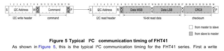
- Addressing: FHT41-TR is specified with 7-bit address 0x45.
- Address statement: the feature list mentions two I²C address options, but the supplied datasheet defines only 0x45 for FHT41-TR and gives no address-selection method.
- Read order: temperature MSB, temperature LSB and CRC are followed by humidity MSB, humidity LSB and CRC.
- Single read: a measurement result can be read only once; the device clears it after acknowledging the first read header.
- Busy behavior: the sensor answers NACK while it is not ready to process a command or read request.
- Transaction end: finish reads with NACK followed by STOP.
Measurement and System Commands
| Command | Returned bytes | Function | Typical use |
|---|---|---|---|
| 0xFD | 6 | Measure temperature and RH, high repeatability | Best repeatability; allow up to 8.3 ms. |
| 0xF6 | 6 | Measure temperature and RH, medium repeatability | Balanced power and repeatability; allow up to 4.5 ms. |
| 0xE0 | 6 | Measure temperature and RH, low repeatability | Lowest average current; allow up to 1.6 ms. |
| 0x89 | 6 | Read unique serial number | Two 16-bit words, each followed by CRC. |
| 0x94 | - | Soft reset | Allow up to 1 ms before the next command. |
| 0x39 | 6 | 200 mW heater for 1 s, then high-repeatability measurement | Highest heating energy. |
| 0x32 | 6 | 200 mW heater for 0.1 s, then high-repeatability measurement | Short high-power pulse. |
| 0x2F | 6 | 110 mW heater for 1 s, then high-repeatability measurement | Medium-power long pulse. |
| 0x24 | 6 | 110 mW heater for 0.1 s, then high-repeatability measurement | Medium-power short pulse. |
| 0x1E | 6 | 20 mW heater for 1 s, then high-repeatability measurement | Low-power long pulse. |
| 0x15 | 6 | 20 mW heater for 0.1 s, then high-repeatability measurement | Low-power short pulse. |
Reset and abort methods
- Soft reset: send command 0x94 to the addressed device.
- General-call reset: send data byte 0x06 to I²C address 0x00; this affects every compatible slave.
- Power-cycle: remove VDD; the source also directs SCL and SDA to be held LOW during power-down.
- Abort: an action can be aborted with soft reset or I²C general-call reset.
CRC Verification and Raw-Data Conversion
Each 16-bit temperature, humidity or serial-number word is followed by one CRC-8 byte. The host should verify every word before using it.
Initialization: 0xFF · Reflect input/output: false · Final XOR: 0x00 · CRC(0xBEEF) = 0x92
Conversion formulas
Temperature: T (°C) = -45 + 175 × ST / (216 - 1)
Temperature: T (°F) = -49 + 315 × ST / (216 - 1)
SRH and ST are unsigned 16-bit raw values assembled most-significant byte first. The humidity equation can produce values below 0 %RH or above 100 %RH; crop to the physical 0 to 100 %RH range when the application does not need uncropped boundary data.
Integrated Heater Operation
The on-chip heater supports nominal power settings of 200 mW, 110 mW and 20 mW at 3.3 V. The command descriptions specify 1 s and 0.1 s pulse options. After the timer expires, the device performs a high-repeatability measurement before switching the heater off.
- Condensation removal: heating can clear condensed or sprayed water that temporarily blocks humidity response.
- High-humidity operation: periodic pulses can reduce long-term creep in persistently humid environments.
- Maximum duty cycle: limit cumulative heater-on time to less than 10% of device operating life.
- Specification validity: normal sensor specifications do not apply while the heater is active.
- Temperature ceiling: base temperature plus heater rise must remain at or below 125 °C.
- Ambient boundary: operate the heater only below 65 °C ambient.
- Supply capability: the highest setting can draw up to 70 mA; prevent supply droop and reset.
- Thermal stress: heater-induced package stress can offset temperature readings.
DFN-4 Package, Land Pattern and Ordering
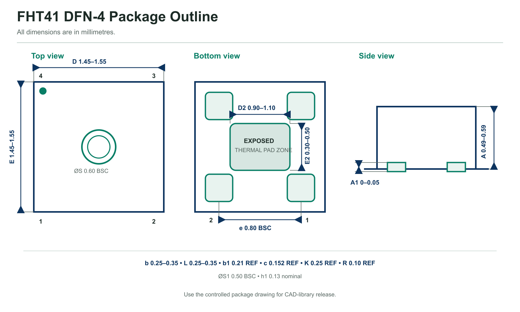
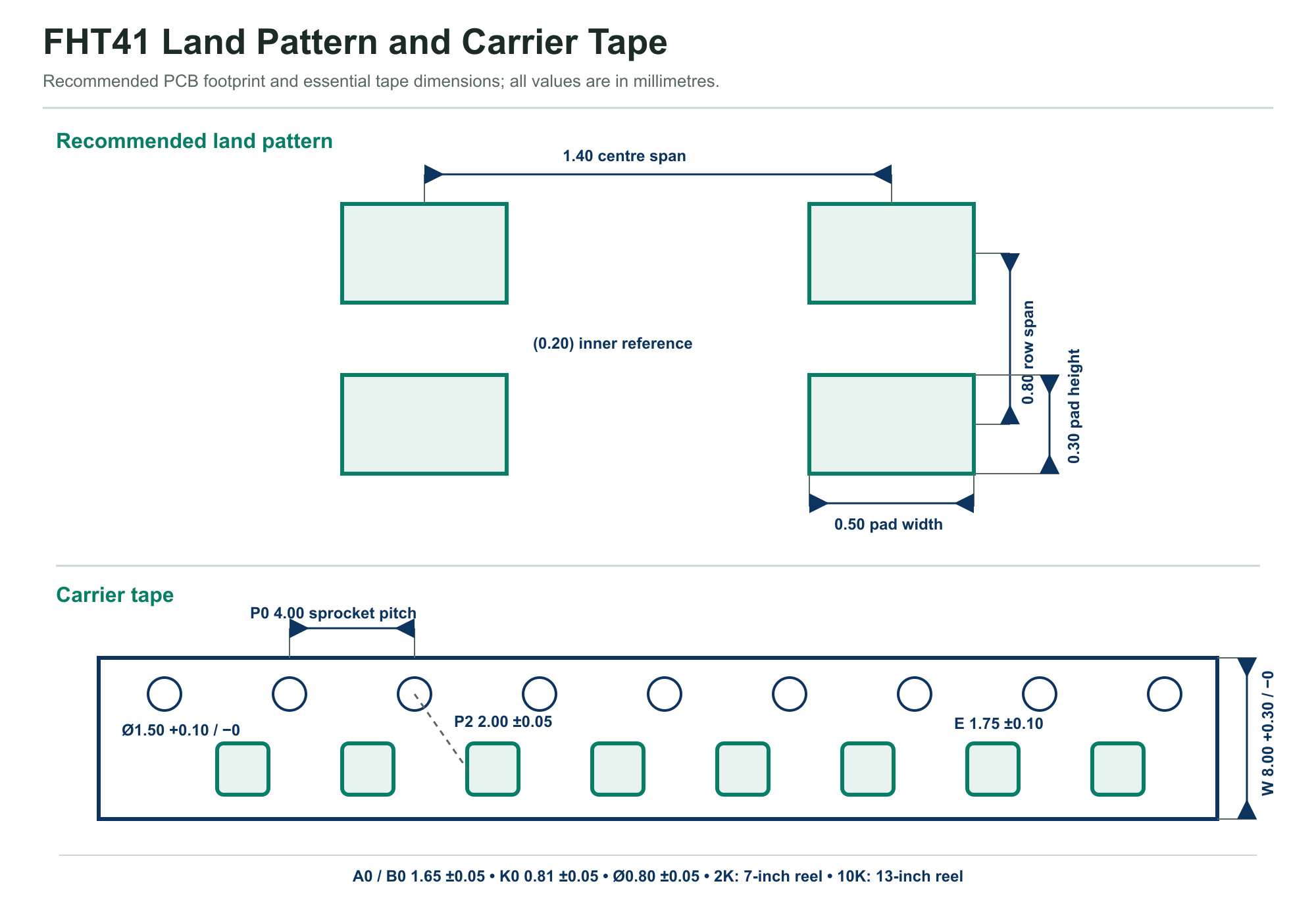
| Dimension | Minimum | Nominal | Maximum | Unit |
|---|---|---|---|---|
| Body width, D | 1.45 | 1.50 | 1.55 | mm |
| Body length, E | 1.45 | 1.50 | 1.55 | mm |
| Overall height, A | 0.49 | 0.54 | 0.59 | mm |
| Standoff, A1 | 0 | 0.02 | 0.05 | mm |
| Lead pitch, e | 0.80 basic | mm | ||
| Lead width, b | 0.25 | 0.30 | 0.35 | mm |
| Inner lead width, b1 | 0.21 reference | mm | ||
| Terminal thickness, c | 0.152 reference | mm | ||
| Exposed-pad width, D2 | 0.90 | 1.00 | 1.10 | mm |
| Exposed-pad length, E2 | 0.30 | 0.40 | 0.50 | mm |
| Lead length, L | 0.25 | 0.30 | 0.35 | mm |
| Sensing aperture, ØS | 0.60 basic | mm | ||
| Inner aperture, ØS1 | 0.50 basic | mm | ||
| Terminal offset, K | 0.25 reference | mm | ||
| Corner radius, R | 0.10 reference | mm | ||
| Aperture recess, h1 | - | 0.13 | - | mm |
Ordering information
| Order code | Device | Package | Standard packing quantity | Note |
|---|---|---|---|---|
| FHT41-TR | FHT41 | DFN4, 1.5 mm × 1.5 mm | 2,000 | High precision, address 0x45, tape and reel |
The marking uses “4X” for the FHT4X family model and YYWWD for year, week and internal version. The package is identified as moisture-sensitivity level MSL1. The tape information specifies a 7-inch reel for 2,000 units and a 13-inch reel for 10,000 units.
Qualification, Storage and Chemical Handling
- ESD controls: handle in an electrostatic-protected area with grounded personnel and conductive objects.
- Avoid volatile chemicals: avoid volatile solvents and organic compounds; the source specifically lists acetone, isopropanol, ethanol and toluene.
- Avoid aggressive media: bases above pH 9, hydrogen peroxide, ammonia and corrosive gases can damage or shift the sensor.
- Control assembly materials: keep solvent, flux, coating, adhesive and cleaning residue away from the sensing surface.
- Allow recovery: after abnormal humidity above 90 %RH or extreme temperatures, return the sensor to a normal environment for recovery.
- Protect solder joints: corrosive gases can first affect interconnects and at higher concentration can damage the sensor.
Application Areas
The supplied datasheet identifies automotive cabins, industrial control, smart homes, consumer electronics and medical devices.
 Automotive CabinCabin comfort and climate monitoring after automotive-system qualification.
 Industrial ControlEnvironmental monitoring near controls, enclosures and production equipment.
 Smart HomeHigh-precision room sensing for comfort control and connected appliances.
 Consumer ElectronicsSmall, low-power sensing for portable and networked products.
 Medical DevicesEnvironmental sensing where the finished device supplies all required validation.
FHT41 Engineering FAQs
What accuracy and range does FHT41 specify?
The source lists typical ±1.8 %RH and ±0.2 °C accuracy, with ranges of 0 to 100 %RH and -40 °C to +125 °C.
What I²C address should firmware use?
The FHT41-TR product and ordering tables specify the 7-bit address 0x45. The feature list mentions two I²C addresses but does not define the second value or a selection method, so confirm alternate-address availability before design-in.
Does FHT41 support clock stretching?
No. If a read is attempted before conversion finishes, the sensor returns NACK. Wait for the selected high, medium or low-repeatability measurement time and retry.
How much current does FHT41 use?
Typical idle current is 0.1 µA. At one measurement per second, the source lists 2 µA for high repeatability, 1.2 µA for medium repeatability and 0.4 µA for low repeatability.
How is data returned?
A measurement read returns six bytes: temperature MSB, temperature LSB and CRC, followed by humidity MSB, humidity LSB and CRC. Measurement data can be read once and is deleted after the first acknowledged read header.
How should the host verify measurements?
Calculate CRC-8 with polynomial 0x31, initialization 0xFF, no reflection and final XOR 0x00 over each 16-bit word. The source check value is CRC(0xBEEF) = 0x92.
What is the heater intended for?
The heater can remove condensation from the sensing surface and support extended operation in high humidity. Keep duty cycle below 10%, ambient below 65 °C and total sensor temperature at or below 125 °C.
What package and ordering code are specified?
FHT41 uses a 1.5 mm × 1.5 mm DFN4 package. The tape-and-reel order code is FHT41-TR with a standard packing quantity of 2,000.
What is the unique serial-number command?
Command 0x89 returns two 16-bit serial-number words, each followed by CRC-8. The serial number is stored in one-time-programmable memory.
Which chemicals must be kept away from the sensor?
Avoid volatile solvents and organic compounds, high-pH bases, hydrogen peroxide, ammonia, corrosive gases, flux, coating, adhesive and cleaning residue at the sensing aperture.
This page summarizes FHT41_datasheet.pdf for component evaluation and engineering reference. It does not replace the complete controlled datasheet. Confirm the current revision, alternate-address definition, heater timing, guaranteed performance, interface timing, package tolerances, assembly process, traceability and qualification requirements before production release.
