
FT18B20 Digital Thermometer
NYFEA FT18B20 combines direct-to-digital temperature measurement, user-selectable 9- to 12-bit resolution, a unique 64-bit ROM code, nonvolatile alarm thresholds, scratchpad memory and CRC-protected 1-Wire communication in a three-lead TO-92 package.
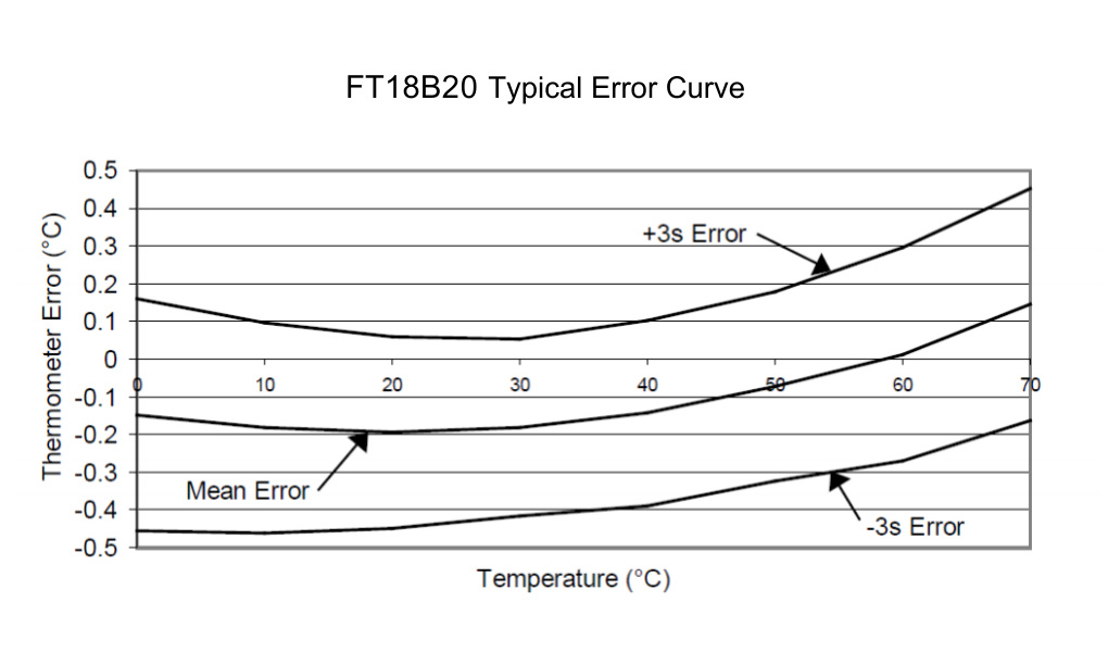
Product scope: the supplied specification lists a -55 °C to +125 °C measurement range, ±0.5 °C accuracy from -10 °C to +70 °C, and 2.5 V to 5.5 V operation. The DC table states ±0.5 °C through +85 °C; this page retains the narrower feature claim until the controlled specification is clarified.
This engineering selection page summarizes the supplied PDF. Use the controlled specification for final limits, timing, package tolerances and production release.
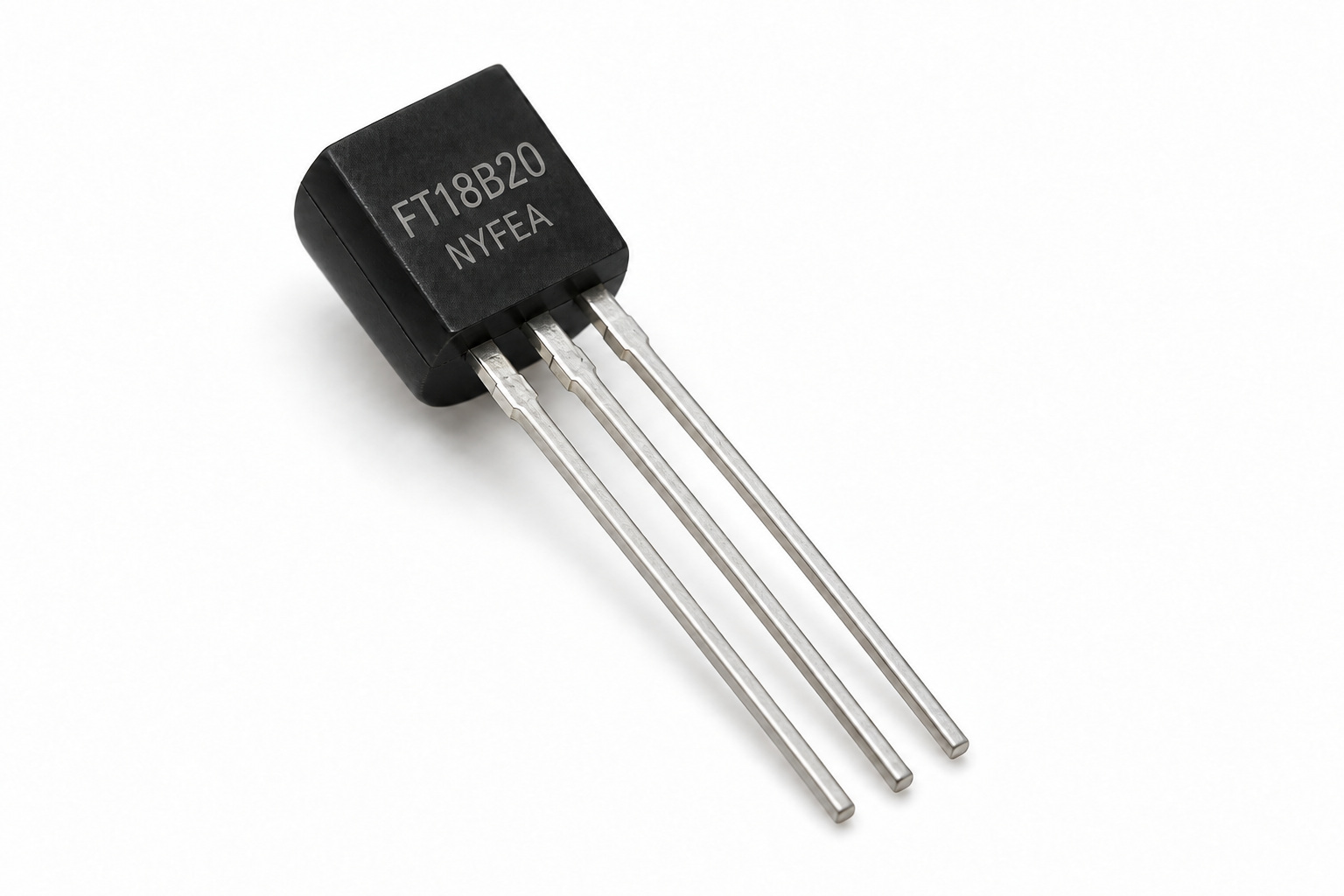
Product Overview and Selection Scope
FT18B20 is intended for direct digital temperature measurement on a single-drop or multidrop 1-Wire bus. Its ROM identity, alarm search, configurable conversion time and optional two-wire parasite-power connection suit distributed temperature sensing.
- Digital temperature: -55 °C to +125 °C measurement range.
- Accuracy: ±0.5 °C from -10 °C to +70 °C in the feature summary; ±1.5 °C over the full range in the DC table.
- Resolution: user-selectable 9, 10, 11 or 12 bits; 12 bits after power-up.
- 1-Wire interface: one DQ signal plus ground, with multidrop device discovery.
- Unique identity: 64-bit ROM with family code 28h, 48-bit serial number and CRC byte.
- Alarm functions: nonvolatile high and low thresholds plus Alarm Search command.
- Power options: 2.5 V to 5.5 V external supply or parasite power from DQ.
- Robustness: the feature list states HBM 7000 V and MM 700 V ESD capability.
Pin Configuration and Functional Architecture
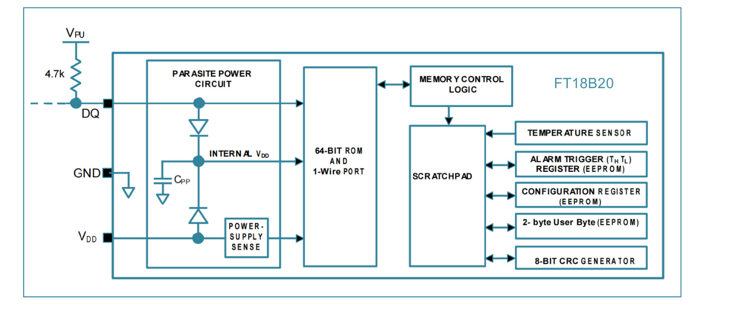
| Pin | Name | Type | Function | Design guidance |
|---|---|---|---|---|
| 1 | GND | Power | Ground reference | Use a low-impedance return to the host and bus pullup supply. |
| 2 | DQ | Bidirectional open drain | 1-Wire data input/output; also supplies parasite power | Use a pullup sized for bus capacitance and timing. Provide a controlled strong pullup when parasite powered. |
| 3 | VDD | Power | Optional 2.5 V to 5.5 V external supply | Connect to GND for parasite-power operation. |
Electrical and Temperature Performance
The DC table applies from -55 °C to +125 °C with VDD from 2.5 V to 5.5 V. Values below reproduce the supplied specification; verify ambiguous column placement against the controlled source before release.
| Parameter | Condition | Minimum | Typical | Maximum | Unit |
|---|---|---|---|---|---|
| Supply voltage, VDD | External power | 2.5 | - | 5.5 | V |
| Pullup supply, VPU | Parasite power | 2.5 | - | 5.5 | V |
| Temperature error | -10 °C to +85 °C, DC table | - | - | ±0.5 | °C |
| Temperature error | -55 °C to +125 °C | - | - | ±1.5 | °C |
| Input LOW, VIL | DQ | -0.3 | - | 0.8 | V |
| Input HIGH, VIH | External power | 2.2 | - | min(5.5, VDD + 0.3) | V |
| Sink current, IL | DQ at 0.4 V | 4.0 | - | - | mA |
| Standby current, IDDS | Up to +70 °C | - | 750 | 1000 | nA |
| Active current, IDD | VDD = 5 V | - | 1.0 | 1.5 | mA |
| Drift | 1000 h at +125 °C, VDD = 5.5 V | - | - | ±0.2 | °C |
Temperature Data, Resolution and Scratchpad Memory
After Convert T [44h], the signed temperature result is placed in scratchpad bytes 0 and 1. At 12-bit resolution, one LSB equals 0.0625 °C. The power-on temperature-register value is +85 °C and should not be treated as a fresh measurement.
| R1 | R0 | Resolution | Temperature increment | Maximum conversion time |
|---|---|---|---|---|
| 0 | 0 | 9 bit | 0.5 °C | 93.75 ms |
| 0 | 1 | 10 bit | 0.25 °C | 187.5 ms |
| 1 | 0 | 11 bit | 0.125 °C | 375 ms |
| 1 | 1 | 12 bit | 0.0625 °C | 750 ms |
Scratchpad map
| Byte | Content | Access and persistence |
|---|---|---|
| 0 | Temperature LSB | Read only; updated by conversion. |
| 1 | Temperature MSB | Read only; signed two's-complement result. |
| 2 | TH alarm threshold | Writable; backed by EEPROM. |
| 3 | TL alarm threshold | Writable; backed by EEPROM. |
| 4 | Configuration register | R1/R0 select resolution; backed by EEPROM. |
| 5 | Reserved | Internal use. |
| 6–7 | User bytes | Writable user EEPROM storage. |
| 8 | Scratchpad CRC | Read only; CRC over bytes 0 through 7. |
1-Wire Signaling and Timing
The bus master initiates reset, write and read time slots. FT18B20 responds to reset with a presence pulse. Data transfers are least-significant bit first.
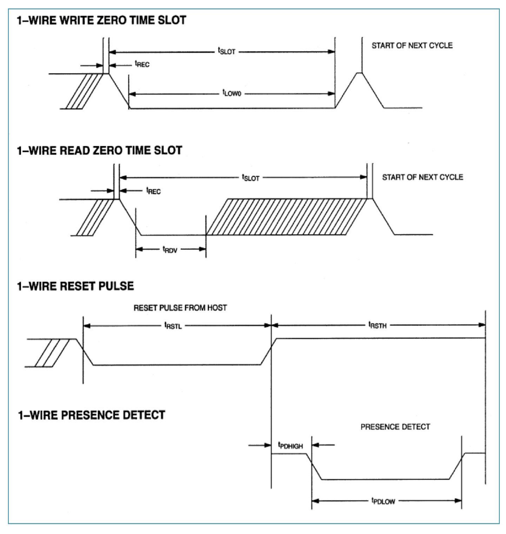
| Timing parameter | Symbol | Minimum | Maximum | Unit |
|---|---|---|---|---|
| Time slot | tSLOT | 60 | 120 | µs |
| Recovery time | tREC | 1 | - | µs |
| Write-0 LOW | tLOW0 | 60 | 120 | µs |
| Write-1 LOW | tLOW1 | 1 | 15 | µs |
| Read data valid | tRDV | - | 15 | µs |
| Reset LOW | tRSTL | 480 | 1000 | µs |
| Reset HIGH | tRSTH | 480 | - | µs |
| Presence-detect HIGH | tPDHIGH | 15 | 60 | µs |
| Presence-detect LOW | tPDLOW | 60 | 240 | µs |
ROM and Function Command Set
ROM commands
| Command | Code | Use | Boundary |
|---|---|---|---|
| Search ROM | F0h | Discover the ROM codes of devices on a multidrop bus. | Repeat the search cycle until every device is identified. |
| Read ROM | 33h | Read one device's 64-bit ROM code. | Use only when exactly one slave is present. |
| Match ROM | 55h | Select one device by its ROM code. | Other devices wait for the next reset. |
| Skip ROM | CCh | Address all devices without a ROM code. | Do not follow with Read Scratchpad on a multidrop bus. |
| Alarm Search | ECh | Discover devices whose latest conversion set an alarm flag. | Run another conversion after changing TH or TL. |
Function commands
| Command | Code | Function | Engineering note |
|---|---|---|---|
| Convert T | 44h | Start one temperature conversion. | Use a strong pullup within 10 µs when parasite powered. |
| Write Scratchpad | 4Eh | Write TH, TL, configuration and user bytes. | Transmit least-significant bit first; complete required bytes before reset. |
| Read Scratchpad | BEh | Read up to nine scratchpad bytes including CRC. | The master may reset early if only part is required. |
| Copy Scratchpad | 48h | Copy writable scratchpad values to EEPROM. | For parasite power, apply strong pullup within 10 µs for at least 10 ms. |
| Recall E² | B8h | Reload EEPROM values into scratchpad. | Read slots return 0 while busy and 1 when complete. |
| Read Power Supply | B4h | Detect parasite-powered devices. | Parasite-powered devices pull DQ LOW during the following read slot. |
External and Parasite Power
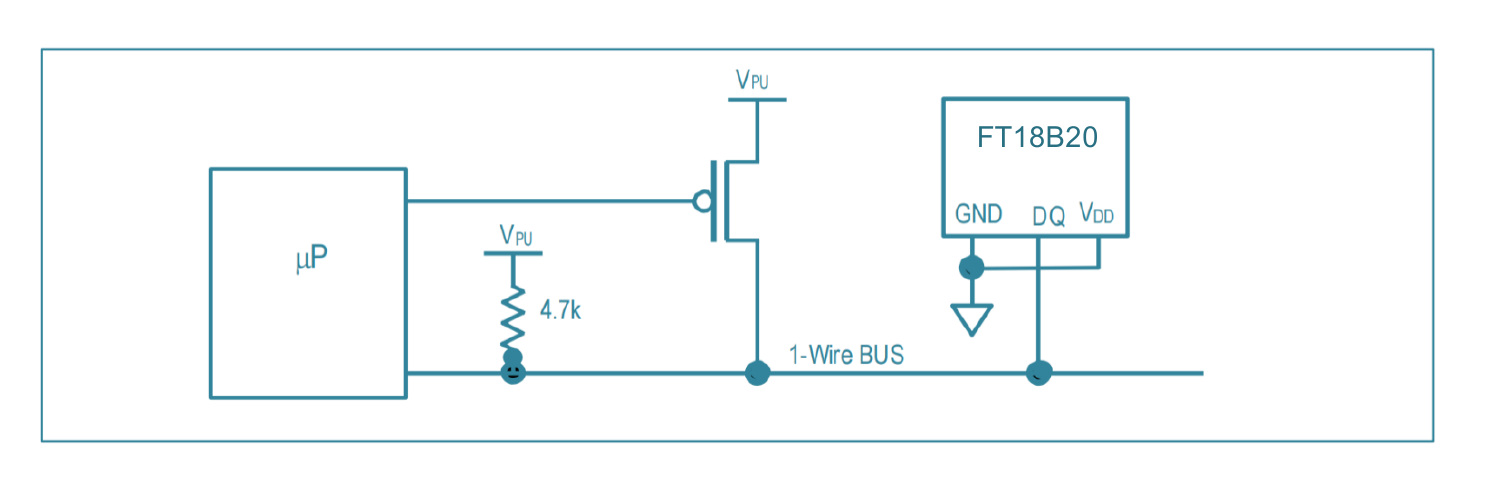
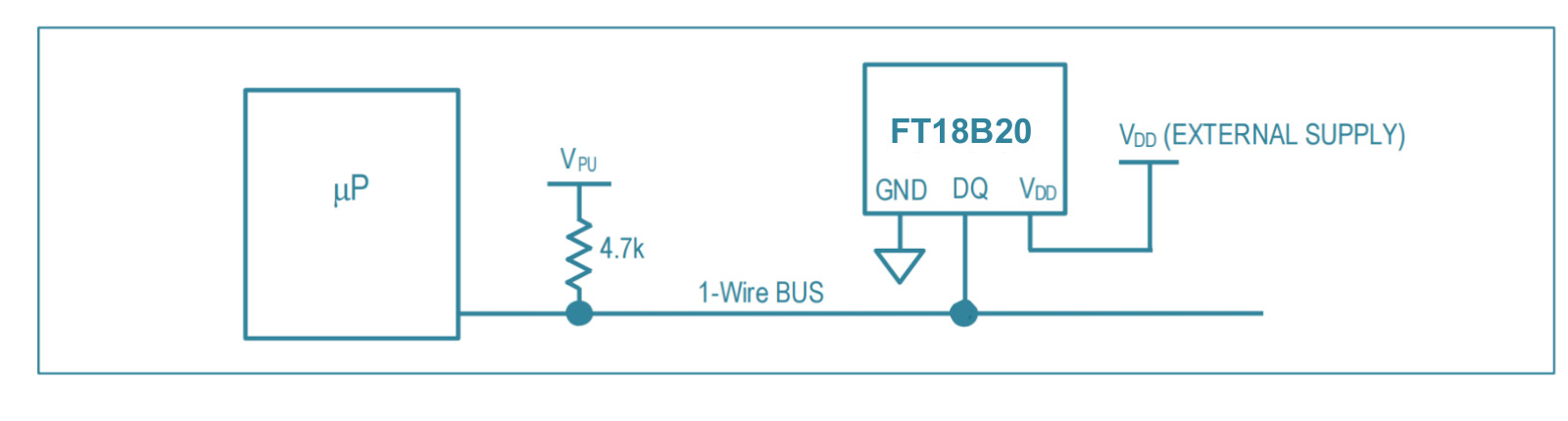
- Strong pullup timing: enable it within 10 µs after Convert T or Copy Scratchpad in parasite mode.
- Bus availability: no other 1-Wire traffic can occur while the strong pullup is active.
- High temperature: parasite power is not recommended above +100 °C because leakage can disrupt communication.
- Mode discovery: use Skip ROM followed by Read Power Supply when the mix of powered devices is unknown.
CRC and Data Integrity
The 64-bit ROM ends with a CRC byte calculated over its first 56 bits. Scratchpad byte 8 contains a CRC over bytes 0 through 7. The master must calculate and compare CRC values before accepting identity, temperature, alarm or configuration data.
Normal polynomial representation: 0x31 · LSB-first reflected implementation: 0x8C
- ROM layout: 8-bit family code 28h, 48-bit serial number, 8-bit CRC.
- Scratchpad: eight data bytes followed by one CRC byte.
- Bit order: feed the least-significant bit first, matching the 1-Wire transfer order.
- Host responsibility: the device does not stop a command sequence when the host detects a CRC mismatch.
TO-92 Package and Ordering
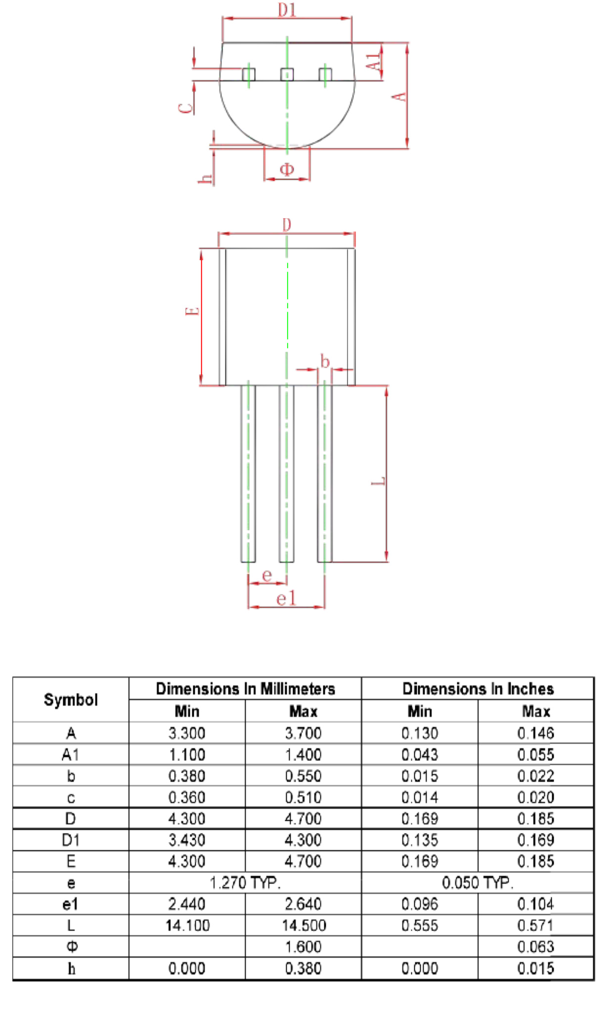
| Symbol | Minimum | Maximum | Unit | Description |
|---|---|---|---|---|
| A | 3.300 | 3.700 | mm | Body profile dimension shown in end view. |
| D | 4.300 | 4.700 | mm | Body width. |
| E | 4.300 | 4.700 | mm | Body height in front view. |
| e | 1.270 typical | mm | Adjacent lead pitch. | |
| e1 | 2.440 | 2.640 | mm | Outer lead span. |
| L | 14.100 | 14.500 | mm | Lead length. |
Ordering information
| Purchase number | Device | Package | Standard packing quantity | Remarks |
|---|---|---|---|---|
| FT18B20 | FT18B20 | TO-92 | 2,000 | Bulk |
Application Guidance and Design Limitations
The supplied specification lists temperature control, industrial systems, consumer goods, grain temperature measurement, thermometers and general thermal systems.
 Temperature ControlClosed-loop control after validating latency, hysteresis, placement and fail-safe behavior.
 Industrial SystemsDistributed monitoring with cable, grounding, surge and EMC validation.
 Consumer GoodsDigital sensing where enclosure gradients and internal heat sources are controlled.
 Grain MonitoringMultidrop probes after cable length, moisture protection and serviceability tests.
 ThermometersDisplay and logging instruments with defined calibration and error handling.
FT18B20 Engineering FAQs
What are the specified FT18B20 temperature range and accuracy?
The feature summary lists -55 °C to +125 °C and ±0.5 °C from -10 °C to +70 °C. The DC table extends its ±0.5 °C line to +85 °C and lists ±1.5 °C over the full range; confirm that discrepancy before publishing a wider accuracy claim.
What supply range does FT18B20 support?
External VDD and parasite-power pullup supply are specified from 2.5 V to 5.5 V.
Can FT18B20 operate with only two wires?
Yes. In parasite-power mode, connect VDD to GND and use DQ plus GND. A strong pullup is required during temperature conversion and EEPROM copy operations.
What resolution should firmware select?
Use 9, 10, 11 or 12 bits to trade conversion time against resolution. Maximum conversion times are 93.75, 187.5, 375 and 750 ms respectively.
How can several FT18B20 devices share one bus?
Each device has a unique 64-bit ROM code. Search ROM discovers devices and Match ROM selects one. Skip ROM can trigger simultaneous conversion, but must not precede Read Scratchpad when several devices could answer.
What does the +85 °C reading mean after power-up?
The temperature register initializes to +85 °C. Firmware should issue Convert T, wait for completion and verify CRC before treating the value as a current measurement.
How does alarm search work?
After each conversion, FT18B20 compares the result with nonvolatile TH and TL thresholds. Alarm Search returns only devices whose latest conversion is at or beyond a programmed threshold.
How is received data checked?
Verify the ROM CRC and the ninth scratchpad byte with polynomial x⁸ + x⁵ + x⁴ + 1. Reject or retry data when the host-calculated CRC does not match.
Is parasite power suitable above +100 °C?
The specification advises against parasite power above +100 °C because increased leakage may prevent reliable communication. Use external VDD where those temperatures are possible.
What package and order quantity are specified?
The ordering table lists FT18B20 in a three-pin TO-92 package, bulk packed with a standard packing quantity of 2,000.
This page summarizes FT18B20_datasheet.pdf for component evaluation and engineering reference. It does not replace the complete controlled product specification. Confirm the current revision, accuracy wording, timing, bus pullup, command sequence, EEPROM endurance, package tolerances, assembly process and qualification requirements before production release.
