
FHT30 Digital Temperature and Humidity Sensor
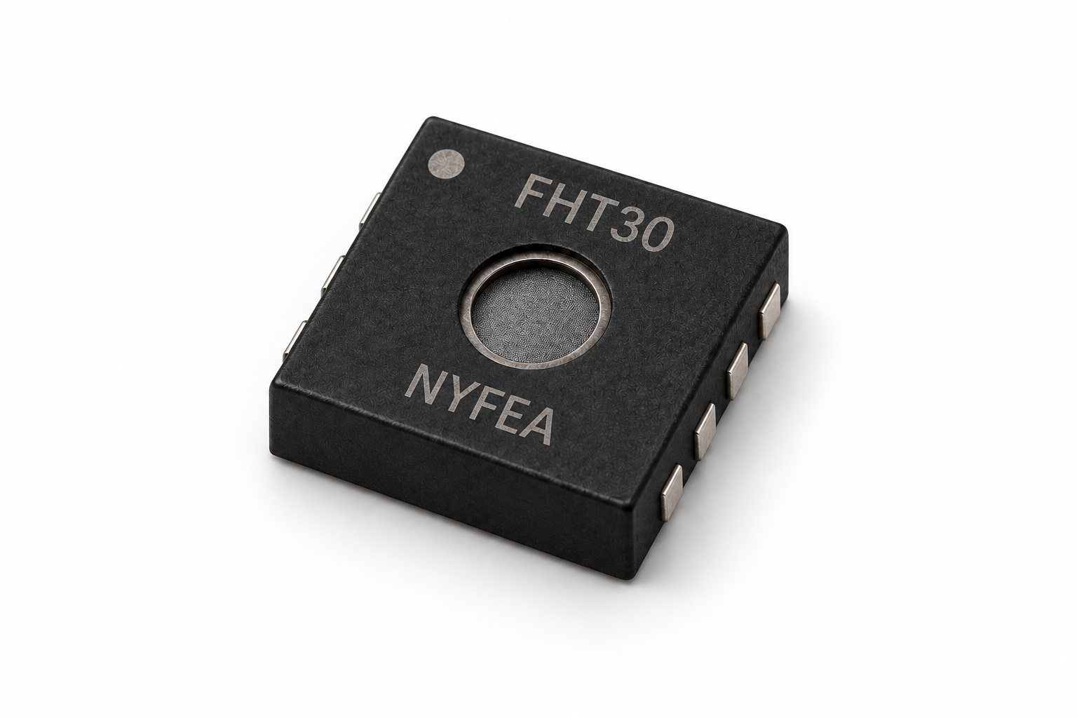
NYFEA FHT30 integrates a MEMS humidity element, temperature sensor, 16-bit ADC, calibration, CRC-protected I²C interface, dual address selection, ALERT output, reset input and heater in a 2.5 mm × 2.5 mm open-cavity DFN-8 package.
Product scope: the supplied specification lists typical accuracy of ±3%RH and ±0.3 °C, a 2.0 V to 5.5 V supply and I²C operation up to 1 MHz. Treat the figures as component-level limits. Validate airflow, thermal coupling, contamination, coating, condensation, firmware timing and fault handling in the complete product.
This engineering page was checked against the supplied FHT30 specification on 2026-09-12. The controlled PDF remains authoritative for curves, footnotes, commands and mechanical release.
Product Overview and Selection Scope
FHT30 targets digital temperature and relative-humidity measurement where dual I²C addresses, periodic acquisition, an alert output and a compact open-cavity package are useful. FHT30 is a board-level sensor, not a sealed probe, complete instrument, safety controller or medical diagnostic device.
- Humidity performance: ±3%RH typical accuracy, 0.01%RH resolution and 0%RH to 100%RH specified range.
- Temperature performance: ±0.3 °C typical accuracy from -40 °C to +90 °C and -45 °C to +130 °C measurement range.
- Dual address: connect ADDR to VSS for 0x44 or VDD for 0x45; never leave ADDR floating.
- Flexible acquisition: single-shot or periodic measurement at 0.5, 1, 2, 4 or 10 measurements per second.
- Data integrity: CRC-8 follows each 16-bit temperature and humidity word.
- Control functions: ALERT output, nRESET input, status register and integrated heater.
- Digital interface: I²C up to 1 MHz, with optional clock stretching in selected single-shot commands.
- Assembly: 2.5 mm × 2.5 mm DFN-8, MSL 1 and 2,000-unit tape-and-reel packing.
Pin Configuration and Functional Architecture
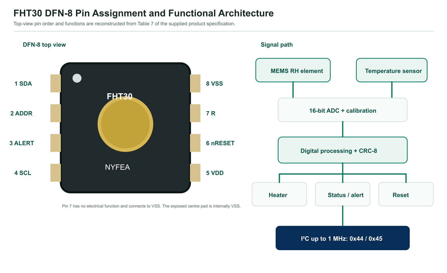
| Pin | Name | Type | Function | PCB guidance |
|---|---|---|---|---|
| 1 | SDA | Bidirectional open-drain | I²C serial data | Pull up to VDD; size the resistor for bus capacitance and timing. |
| 2 | ADDR | Digital input | Selects 0x44 or 0x45 | Tie to VSS or VDD; do not float or change during communication. |
| 3 | ALERT | Digital output | Signals threshold status | Connect only to a suitable logic input or transistor gate; leave floating if unused. |
| 4 | SCL | Bidirectional open-drain | I²C serial clock | Pull up to VDD; selected commands may stretch the clock. |
| 5 | VDD | Power | 2.0 V to 5.5 V supply | Place a 100 nF bypass capacitor close to VDD and VSS. |
| 6 | nRESET | Digital input, active LOW | Hardware reset | Internal pull-up; leave floating or add >2 kΩ to VDD if unused. |
| 7 | R | No electrical function | Reserved package contact | Connect to VSS as specified. |
| 8 | VSS | Power | Ground | Use a short return; the centre die pad is internally connected to VSS. |
| Centre pad | Die pad | Thermal/mechanical | Internally VSS | Solder for mechanical-stress control; follow the recommended land pattern. |
Relative-Humidity and Temperature Performance
| RH parameter | Condition | Value | Unit |
|---|---|---|---|
| Typical accuracy | Specified reference condition | ±3 | %RH |
| Repeatability | High / medium / low | 0.10 / 0.15 / 0.25 | %RH |
| Resolution | Typical | 0.01 | %RH |
| Hysteresis | +25 °C | ±0.8 | %RH |
| Measurement range | Specified | 0 to 100 | %RH |
| Response time, t63% | Sensor reference | 8 | s |
| Long-term stability | Typical | <0.25 | %RH/year |
| Temperature parameter | Condition | Value | Unit |
|---|---|---|---|
| Typical accuracy | -40 °C to +90 °C | ±0.3 | °C |
| Repeatability | High / medium / low | 0.06 / 0.12 / 0.24 | °C |
| Resolution | Typical | 0.015 | °C |
| Measurement range | Specified | -45 to +130 | °C |
| Response time, t63% | Sensor reference | >2 | s |
| Long-term stability | Maximum stated | <0.03 | °C/year |
Electrical Characteristics and Measurement Timing
Unless a row states otherwise, typical electrical values refer to +25 °C. Minimum and maximum values cover the stated operating limits in the source table.
| Parameter | Condition | Minimum | Typical | Maximum | Unit |
|---|---|---|---|---|---|
| Supply voltage, VDD | Operating | 2.0 | 3.3 | 5.5 | V |
| Power-on reset level, VPOR | Supply threshold | 1.8 | 1.9 | 2.0 | V |
| Supply slew rate | VDD,slew | - | - | 20 | V/ms |
| Idle current | Single-shot, +25 °C | - | 0.2 | 2.0 | µA |
| Measurement current | During conversion | - | 600 | 1500 | µA |
| Average current | 1 Hz, low repeatability, single-shot | - | 1.7 | - | µA |
| Heater power | Heater active | 3.6 | - | 33 | mW |
| Bus capacitance | Cb | - | - | 400 | pF |
Measurement timing by supply range
| Operation | Supply or mode | Typical | Maximum | Unit |
|---|---|---|---|---|
| Power-up | 2.4 V to 5.5 V | 0.5 | 1.0 | ms |
| Power-up | 2.2 V to 2.4 V | 0.5 | 1.5 | ms |
| Soft reset | Reset command | 0.5 | 1.5 | ms |
| Measurement | Low repeatability, 2.4 V to 5.5 V | 2.5 | 4.0 | ms |
| Measurement | Low repeatability, 2.2 V to 2.4 V | 2.5 | 4.5 | ms |
| Measurement | Medium repeatability, 2.4 V to 5.5 V | 4.5 | 6.0 | ms |
| Measurement | Medium repeatability, 2.2 V to 2.4 V | 4.5 | 6.5 | ms |
| Measurement | High repeatability | 12.5 | 15.5 | ms |
| nRESET LOW pulse | Hardware reset | - | Minimum 1 | µs |
I²C Address Selection, Measurement Readout and CRC-8
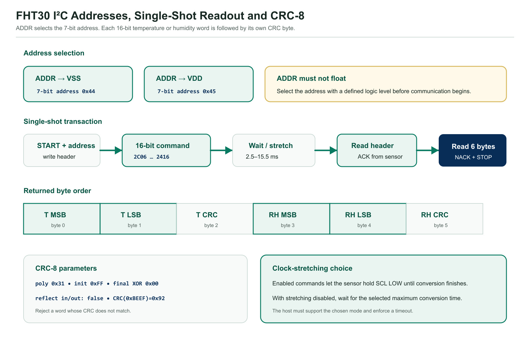
FHT30 supports two 7-bit addresses. ADDR tied to VSS selects 0x44; ADDR tied to VDD selects 0x45. A measurement read returns temperature MSB, temperature LSB, temperature CRC, humidity MSB, humidity LSB and humidity CRC.
Single-Shot and Periodic Commands, Data Fetch and Conversion
| Mode | Condition | High | Medium | Low |
|---|---|---|---|---|
| Single shot, clock stretching enabled | One conversion | 0x2C06 | 0x2C0D | 0x2C10 |
| Single shot, clock stretching disabled | One conversion | 0x2400 | 0x240B | 0x2416 |
| Periodic, 0.5 mps | 0.5 measurement/s | 0x2032 | 0x2024 | 0x202F |
| Periodic, 1 mps | 1 measurement/s | 0x2130 | 0x2126 | 0x212D |
| Periodic, 2 mps | 2 measurements/s | 0x2236 | 0x2220 | 0x222B |
| Periodic, 4 mps | 4 measurements/s | 0x2334 | 0x2322 | 0x2329 |
| Periodic, 10 mps | 10 measurements/s | 0x2737 | 0x2721 | 0x272A |
Periodic-mode control
| Command | Hex code | Host action |
|---|---|---|
| Fetch periodic data | 0xE000 | Read six bytes if new data are present; NACK means no result is available. |
| Stop periodic acquisition | 0x3093 | Stop periodic mode before sending commands other than fetch; allow 1 ms for transition. |
Temperature: T = -45 + 175 × ST / 65535 °C
SRH and ST are unsigned 16-bit raw values. Validate CRC before applying either conversion.
Status Register, Heater and Reset Control
| Command | Hex code | Function | Release check |
|---|---|---|---|
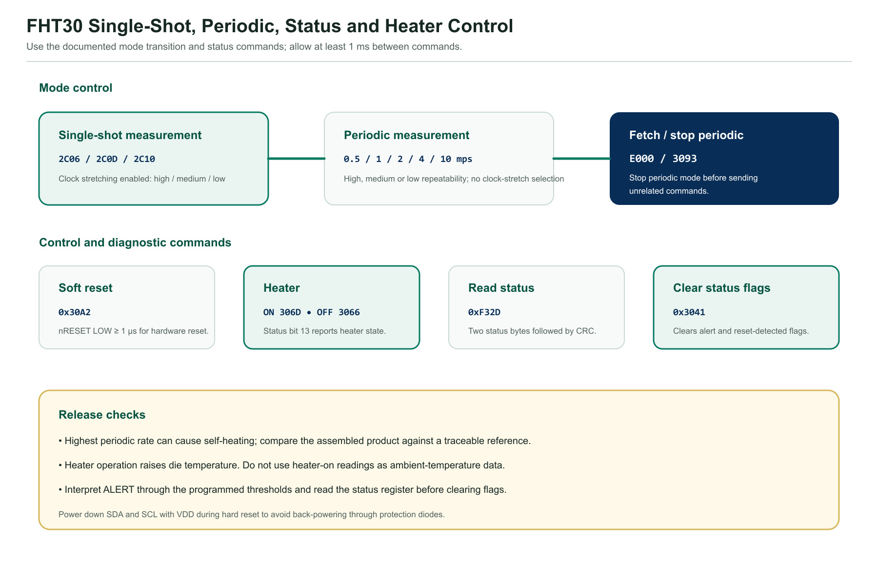
| Soft reset | 0x30A2 | Reloads internal state and calibration data | Issue only from idle; allow up to 1.5 ms. |
| General-call reset | 0x0006 | Resets compatible devices at address 0x00 | Not device-specific; assess every bus participant. |
| Heater enable | 0x306D | Turns the internal heater on | Heater changes die temperature and RH around the opening. |
| Heater disable | 0x3066 | Turns the internal heater off | Allow thermal recovery before ambient-temperature use. |
| Read status register | 0xF32D | Returns 16 status bits plus CRC | Check alert, heater, reset, command and write-CRC states. |
| Clear status flags | 0x3041 | Clears alert and reset-detected flags | Log diagnostic state before clearing it. |
Typical Application Circuit, PCB Placement and Contamination Control
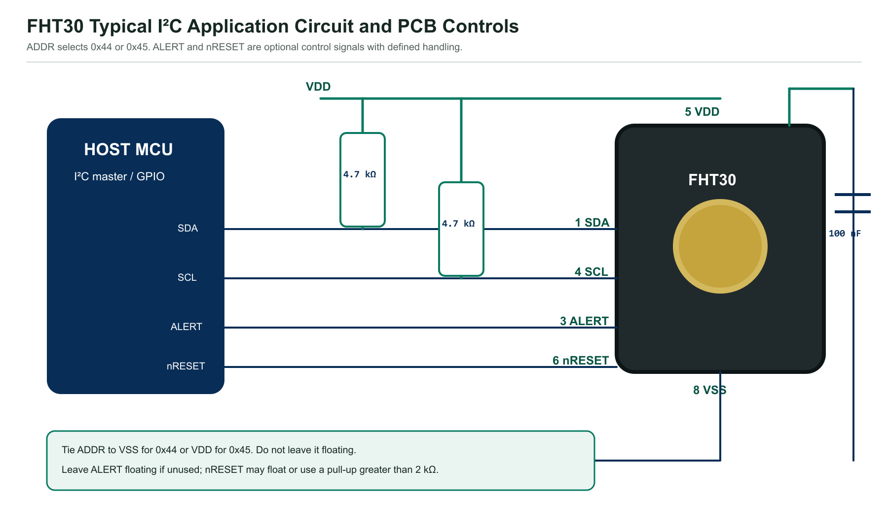
- Place away from heat: isolate FHT30 from processors, regulators, displays, charging circuits, batteries and high-current copper.
- Expose representative air: provide a short, open diffusion path without a stagnant enclosure pocket.
- Protect the opening: do not allow flux, wash fluid, dust, adhesive or conformal coating to contact the sensing cavity.
- Use the supplied film correctly: the FHT30-TR ordering note specifies a dustproof breathable film; do not remove a permanent dust film.
- Control the bus: calculate pull-ups from VDD, capacitance, rise time and VOL rather than copying one value to every design.
- Validate thermal error: compare the assembled product against a traceable reference at steady state and during power transitions.
DFN-8 Package, Land Pattern, Stencil and Tape-and-Reel Data
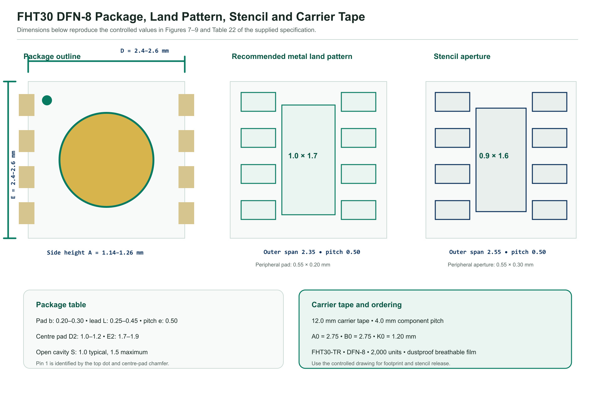
| Item | Specified value | Release note |
|---|---|---|
| Ordering code | FHT30-TR | Tape and reel with dustproof breathable film. |
| Package | DFN-8, 2.5 mm × 2.5 mm | Open cavity centred on top; exposed centre pad on bottom. |
| Package height | 1.14 mm to 1.26 mm | 1.20 mm typical. |
| Top mark | HT30 + YYWWD | Top dot identifies pin 1; date and product code support traceability. |
| Standard packing quantity | 2,000 units | 12 mm carrier tape, 4 mm component pitch. |
| Moisture sensitivity | MSL 1 | Source document cites IPC/JEDEC J-STD-020. |
| Quality statement | JESD47; RoHS | Confirm current qualification evidence for the required market. |
Application Guidance and Design Limitations
The FHT30 specification lists communication equipment, photovoltaic energy storage, consumer electronics, cold-chain transportation, smart home and smart agriculture. The five categories below focus on distinct placement and validation problems rather than repeating the same generic use case.
 Communications EquipmentMonitor cabinet air while isolating the sensor from processor and power-converter heat.
 PV Energy StorageMeasure enclosure conditions with condensation, corrosive gas, coating and high-voltage isolation controls.
 Consumer ElectronicsCompact sensing for monitors and controls after self-heating and enclosure-response verification.
 Cold-Chain TransportValidate low-temperature accuracy, condensation recovery, airflow and logger response time.
 Smart AgricultureProtect against spray, dust, fertilizer vapour and prolonged high humidity in greenhouse nodes.
FHT30 Engineering FAQs
What accuracy does FHT30 specify?
FHT30 specifies typical accuracy of ±3%RH and ±0.3 °C. The temperature value applies from -40 °C to +90 °C; maximum tolerance depends on operating temperature and humidity and must be checked against the specification curves.
What supply voltage and I²C speed does FHT30 support?
FHT30 operates from 2.0 V to 5.5 V and supports I²C clock rates up to 1 MHz. The bus timing, rise time, pull-up resistance and host clock-stretch behavior must meet the selected operating mode.
What I²C addresses does FHT30 use?
FHT30 uses 7-bit address 0x44 when ADDR is tied to VSS and 0x45 when ADDR is tied to VDD. ADDR must not be left floating or switched during a transaction.
Can two FHT30 sensors share one I²C bus?
Yes. One FHT30 can use 0x44 and a second FHT30 can use 0x45 on the same bus. Verify total bus capacitance, pull-up current and address strapping on the assembled board.
Does FHT30 support clock stretching?
Yes, but only selected single-shot commands enable clock stretching. Periodic mode does not offer a clock-stretch selection. If the host cannot accept SCL being held LOW, use a non-stretch command and wait for the specified maximum conversion time.
How is FHT30 measurement data protected?
FHT30 appends an 8-bit CRC to each 16-bit temperature and humidity word. The CRC uses polynomial 0x31, initialization 0xFF, no input or output reflection, and final XOR 0x00.
How fast can FHT30 measure?
Low-repeatability single-shot conversion is typically 2.5 ms and at most 4.0 ms above 2.4 V, or 4.5 ms from 2.2 V to 2.4 V. High repeatability is typically 12.5 ms and at most 15.5 ms.
What is the difference between single-shot and periodic mode?
Single-shot mode converts once per command and can enable or disable clock stretching. Periodic mode runs at 0.5, 1, 2, 4 or 10 measurements per second; use 0xE000 to fetch data and 0x3093 to stop periodic acquisition before unrelated commands.
What external components does FHT30 need?
Place a 100 nF decoupling capacitor close to VDD and VSS and provide I²C pull-ups on SDA and SCL. The reference text recommends 4.7 kΩ as a starting value, but the final resistance must meet actual bus capacitance, rise time and sink-current limits.
How should unused ALERT and nRESET pins be handled?
Leave ALERT floating when the alarm function is unused. The internally pulled-up nRESET pin may be left floating or pulled up to VDD with a resistor greater than 2 kΩ; a hardware reset requires at least a 1 µs LOW pulse.
What package and ordering code does FHT30 use?
FHT30-TR uses a 2.5 mm × 2.5 mm DFN-8 package, 2,000 units per reel, with a dustproof breathable film. The package height is 1.14 mm to 1.26 mm and the centre sensing cavity is on the top surface.
Can conformal coating or solvents contact FHT30?
Do not coat or contaminate the sensing opening. Volatile solvents and organic compounds can cause humidity offset. For board coating, use the specified temporary protective film, keep spray at least 30 cm away, allow about 24 hours for full drying, then remove the film before normal sensing.
This page summarizes FHT30_datasheet.pdf for component selection and implementation. It does not replace the controlled product specification. Confirm the current revision, accuracy curves, threshold-command documentation, ordering code, package drawing, assembly process and qualification evidence before production release.
