
FHT40 Digital Temperature and Humidity Sensor
NYFEA FHT40 combines a capacitive relative-humidity sensing element, temperature sensor, signal conditioning, calibration memory, digital processing, CRC-protected I²C interface and configurable on-chip heater in a 1.5 mm × 1.5 mm DFN-4 package.
Product scope: the supplied specification lists typical accuracy up to ±1.8 %RH and ±0.2 °C, 1.6 V to 5.5 V operation and I²C up to 1 MHz. Accuracy depends on environmental exposure, placement, thermal coupling, airflow, chemical contamination, condensation, assembly and host implementation. Validate the finished product under its real operating conditions.
This page is an engineering selection summary. The controlled PDF remains the authority for limits, curves, footnotes, package tolerances and production release.
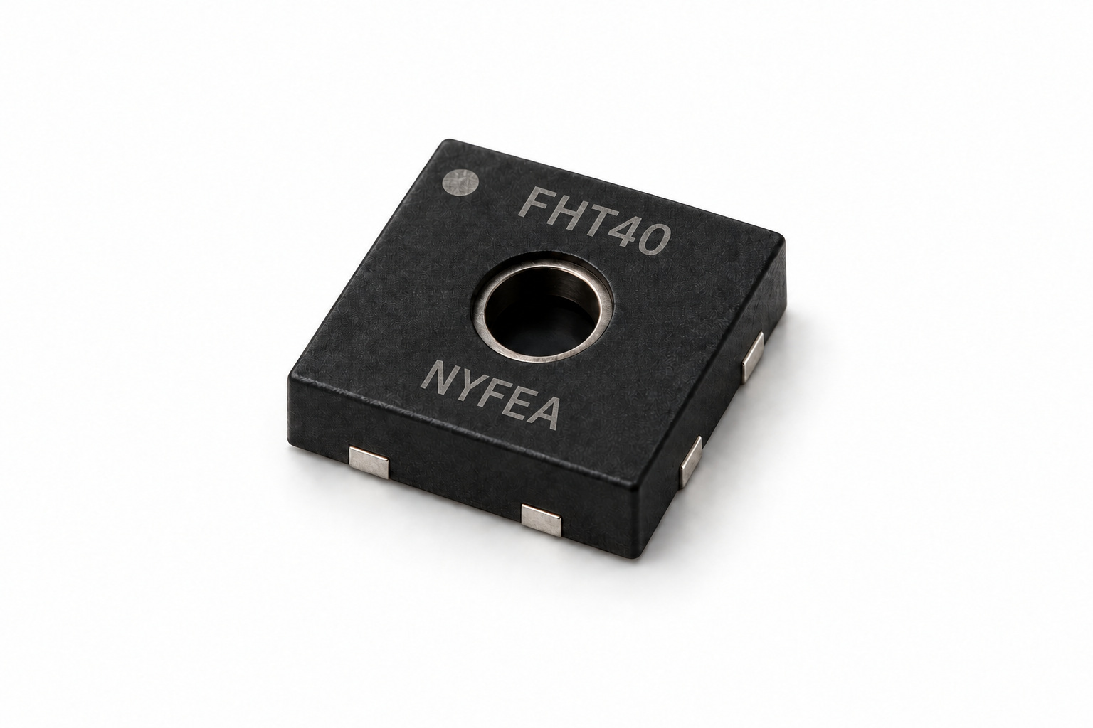
Product Overview and Selection Scope
FHT40 is intended for compact digital temperature and relative-humidity measurement where low average current, CRC-protected output and a controllable recovery heater are useful. The finished system must provide the enclosure, environmental protection, calibration policy and safety functions required by its application.
- Relative humidity: 0 %RH to 100 %RH specified range, 0.01 %RH resolution and ±1.8 %RH typical accuracy.
- Temperature: -40 °C to +125 °C specified range, 0.01 °C resolution and ±0.2 °C typical accuracy.
- Low power: 0.1 µA typical idle current; 0.4 µA average at 1 Hz in low-repeatability mode.
- Repeatability choices: high, medium and low modes trade measurement time against repeatability and current.
- Digital integrity: CRC-8 protects each temperature and humidity word during I²C readout.
- Integrated heater: three power levels and two durations for condensation removal and high-humidity recovery.
- Traceability and qualification: the feature list states NIST traceability and JEDEC JESD47 qualification.
- Compact assembly: 1.5 mm × 1.5 mm DFN-4, MSL 1, tape-and-reel ordering.
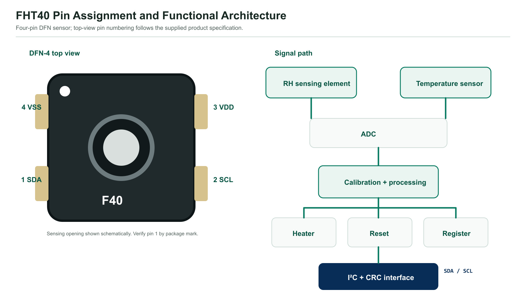
Pin Configuration and Functional Architecture
| Pin | Name | Type | Function | PCB guidance |
|---|---|---|---|---|
| 1 | SDA | Bidirectional digital | I²C serial data | Open-drain bus; connect to VDD through the selected pull-up resistor. |
| 2 | SCL | Digital input | I²C serial clock | Connect to VDD through the selected pull-up resistor; the sensor does not clock-stretch. |
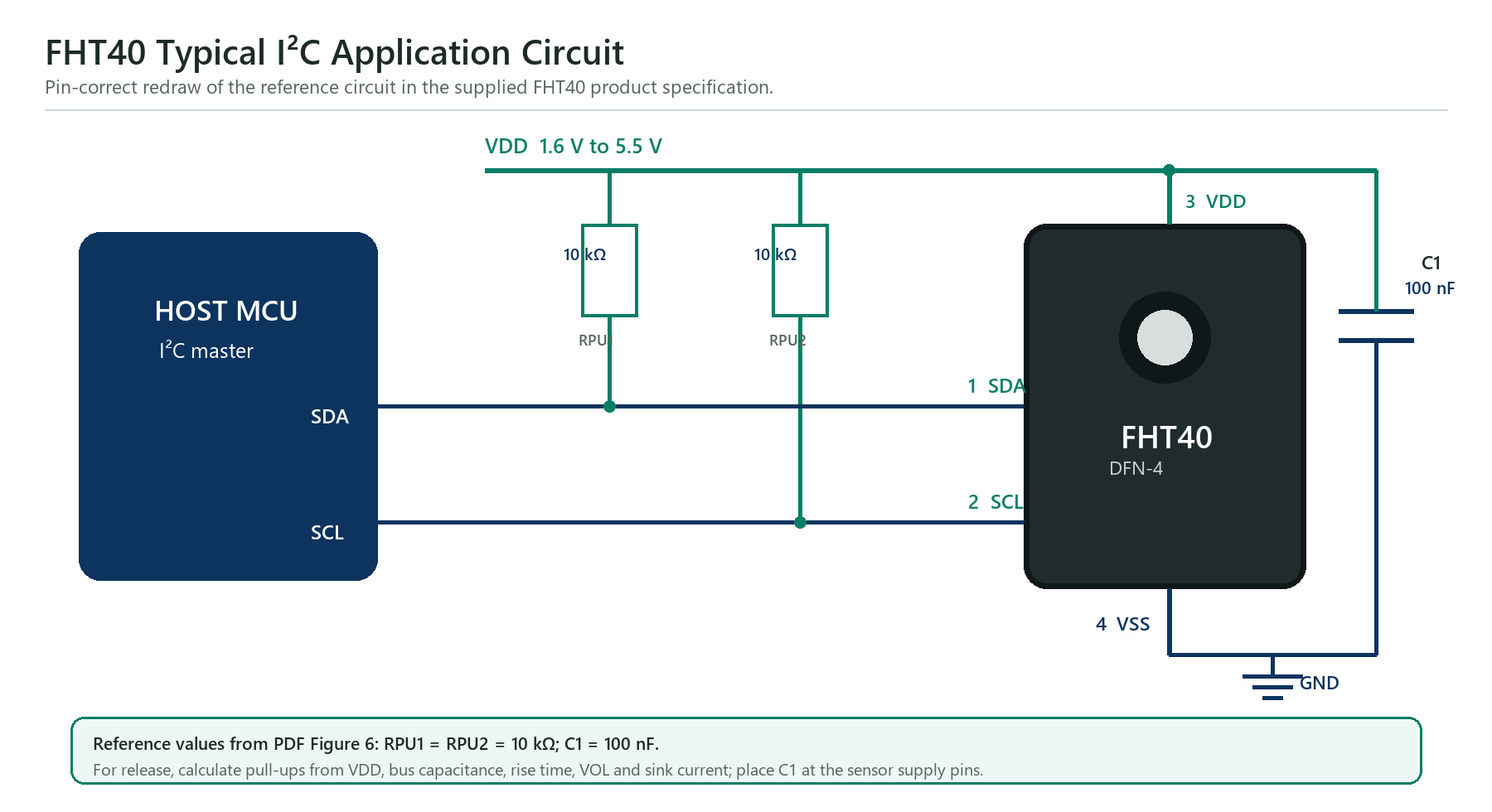
| 3 | VDD | Power | 1.6 V to 5.5 V supply | Place the 100 nF bypass capacitor beside VDD and VSS. |
| 4 | VSS | Power | Ground reference | Use a short, low-impedance return and keep heat sources away from the sensor. |
Electrical Characteristics and Measurement Timing
Unless otherwise stated, the electrical table applies across -40 °C to +125 °C and VDD from 1.6 V to 5.5 V. Typical conditions are +25 °C and 3.3 V.
| Parameter | Condition | Minimum | Typical | Maximum | Unit |
|---|---|---|---|---|---|
| Supply voltage, VDD | Operating | 1.6 | 3.3 | 5.5 | V |
| Power-on reset level, VPOR | Supply threshold | 0.8 | - | 1.0 | V |
| Supply slew rate | VDD,slew | - | - | 20 | V/ms |
| Idle current | No measurement active | 0.08 | 0.10 | 0.15 | µA |
| Measurement current | During conversion | - | 300 | 500 | µA |
| Average current | High / medium / low repeatability | - | 2.0 / 1.2 / 0.4 | - | µA |
| LOW input voltage, VIL | SDA or SCL | 0 | - | 0.3 × VDD | V |
| HIGH input voltage, VIH | SDA or SCL | 0.7 × VDD | - | VDD | V |
| Pull-up resistance, RP | SDA or SCL; no additional source-table condition | 390 | - | - | Ω |
| Bus capacitance | Cb | - | - | 400 | pF |
Absolute maximum ratings and robustness
| Parameter | Minimum | Maximum / rating | Unit | Engineering interpretation |
|---|---|---|---|---|
| Operating-condition temperature | -40 | +125 | °C | Listed in the absolute-maximum table; performance still follows the specified measurement limits and curves. |
| Junction temperature | - | +150 | °C | Stress limit. |
| Storage temperature | -40 | +150 | °C | Stress limit; recommended storage conditions are narrower. |
| HBM electrostatic discharge | - | ±7000 | V | Per ANSI/ESDA/JEDEC JS-001. |
| Latch-up | - | ±200 | mA | Per JESD78, Class IA. |
Absolute maximum ratings define stress boundaries and do not guarantee normal operation or measurement accuracy at those limits.
System timing
| Operation | Mode or condition | Typical | Maximum | Unit |
|---|---|---|---|---|
| Power-up | After hard reset and VDD > VPOR | 0.3 | 1.0 | ms |
| Soft reset | Command 0x94 | - | 1.0 | ms |
| Measurement | Low repeatability | 1.3 | 1.6 | ms |
| Measurement | Medium repeatability | 3.7 | 4.5 | ms |
| Measurement | High repeatability | 6.9 | 8.3 | ms |
| Heater pulse | Short / long command | 0.1 / 1.0 | Defined by command | s |
Relative-Humidity and Temperature Performance
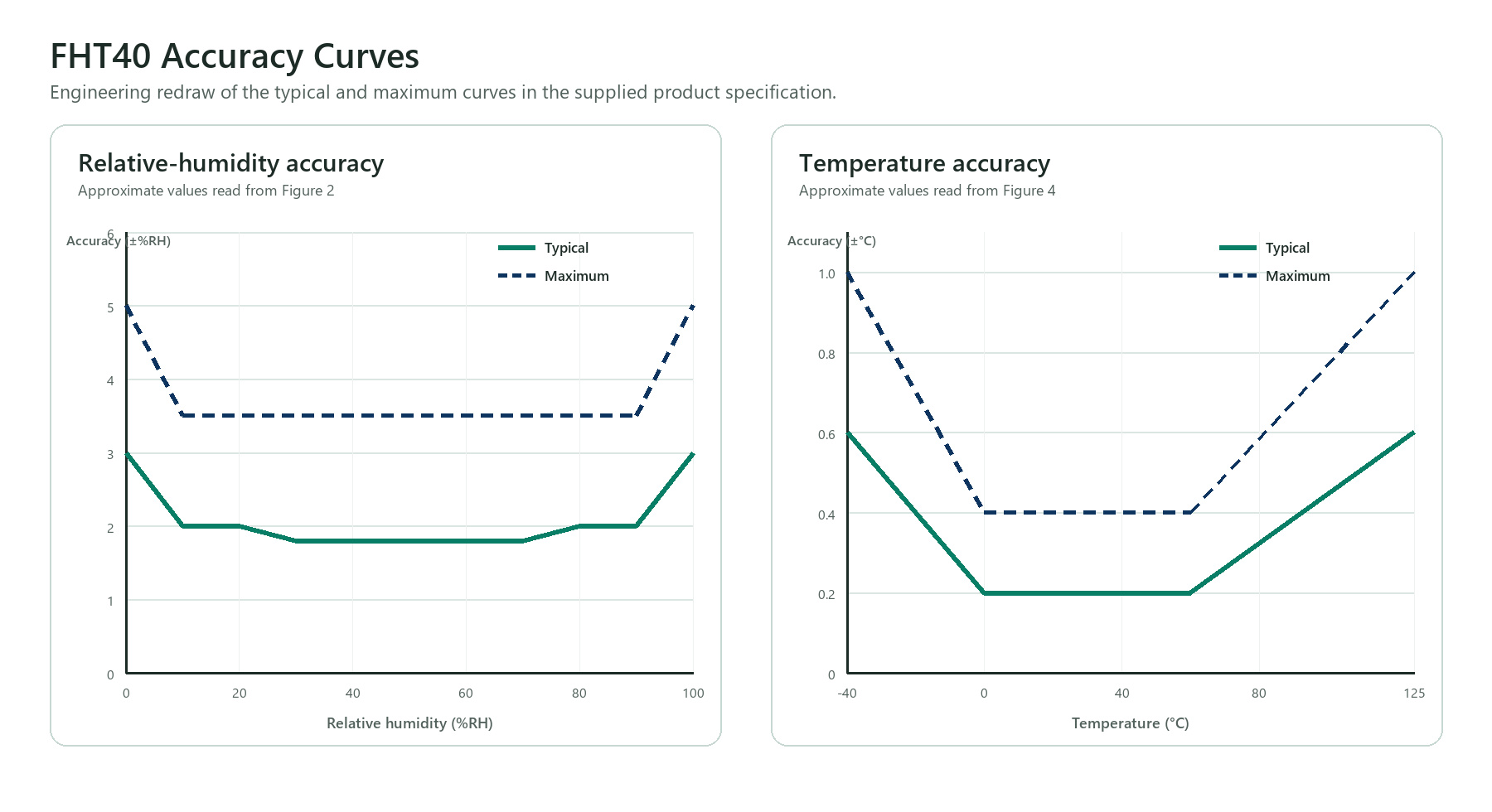
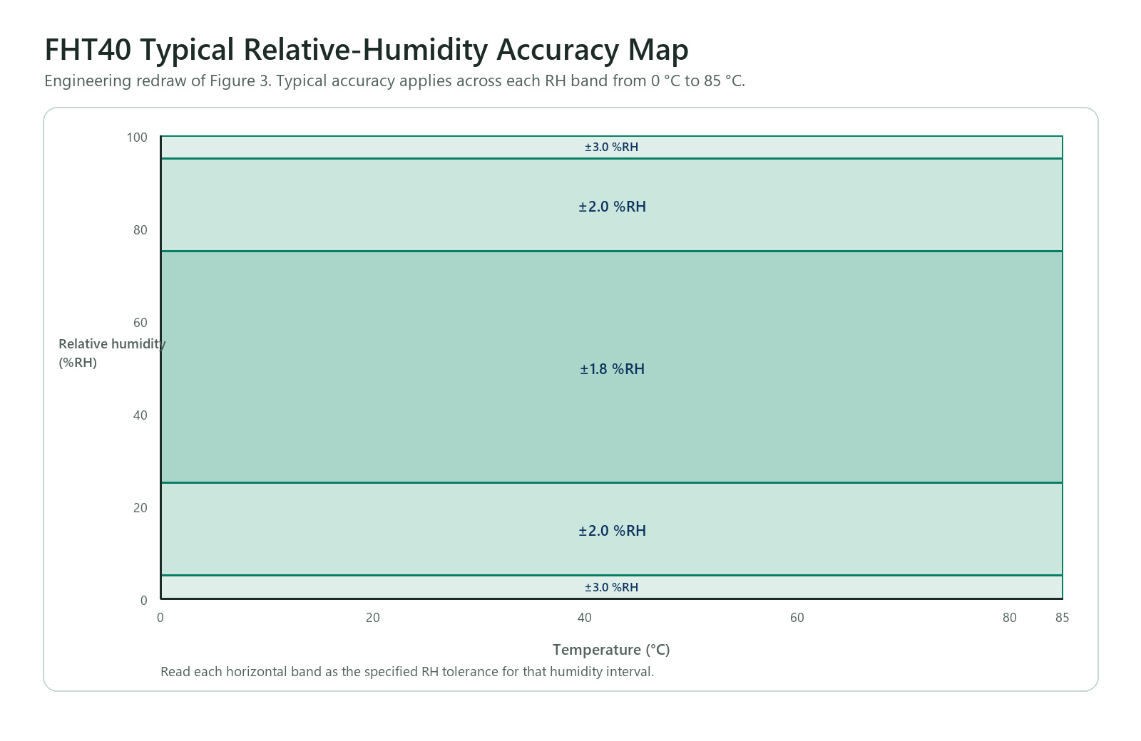
The tabulated values below are sensor-level specifications. The curves show how typical and maximum accuracy change near the ends of the measurement ranges, and the typical-accuracy tolerance map defines the FHT40 relative-humidity bands from 0 °C to 85 °C.
| RH parameter | Value | Unit |
|---|---|---|
| Typical accuracy | ±1.8 | %RH |
| Repeatability, high / medium / low | 0.08 / 0.15 / 0.25 | %RH |
| Resolution | 0.01 | %RH |
| Hysteresis at +25 °C | ±0.8 | %RH |
| Specified range | 0 to 100 | %RH |
| Response time, t63% | 4 | s |
| Typical long-term drift | <0.3 | %RH/year |
| Temperature parameter | Value | Unit |
|---|---|---|
| Typical accuracy | ±0.2 | °C |
| Repeatability, high / medium / low | 0.04 / 0.07 / 0.10 | °C |
| Resolution | 0.01 | °C |
| Specified range | -40 to +125 | °C |
| Response time, t63% | 2 | s |
| Typical long-term drift | <0.03 | °C/year |
I²C Communication, Measurement Readout and CRC-8
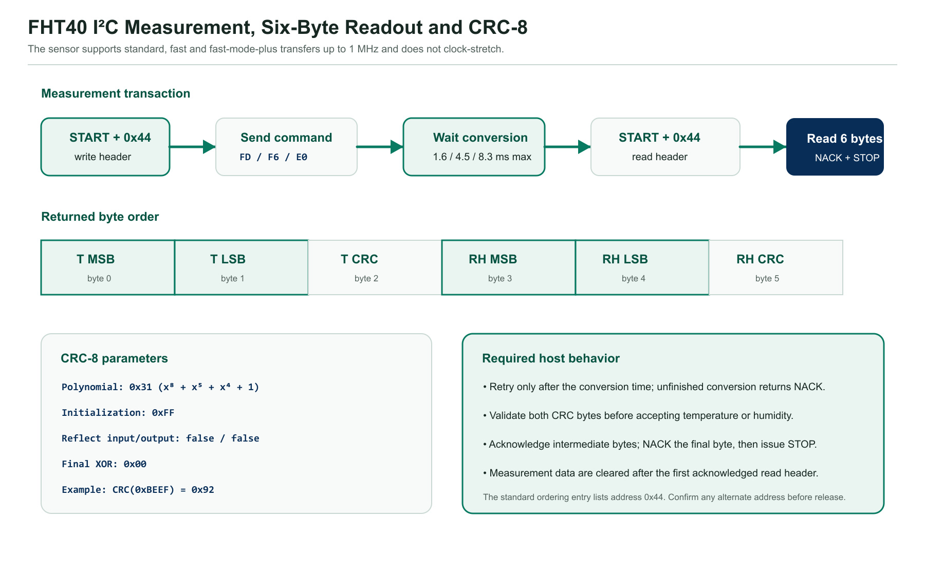
Every transfer starts with START and ends with STOP. The host writes one command, waits for conversion, then reads temperature MSB/LSB/CRC followed by humidity MSB/LSB/CRC. The final byte is terminated with NACK and STOP. An acknowledged read header clears the stored measurement after that read, so the host must validate and retain the complete six-byte frame.
Command Set, Raw-Value Conversion and Reset
| Command | Function | Returned bytes | Engineering note |
|---|---|---|---|
| 0xFD | Measure T and RH, high repeatability | 6 | Maximum measurement time 8.3 ms. |
| 0xF6 | Measure T and RH, medium repeatability | 6 | Maximum measurement time 4.5 ms. |
| 0xE0 | Measure T and RH, low repeatability | 6 | Maximum measurement time 1.6 ms. |
| 0x89 | Read unique serial number | 6 | Two 16-bit words, each followed by CRC. |
| 0x94 | Soft reset | ACK | Allow up to 1 ms before the next command. |
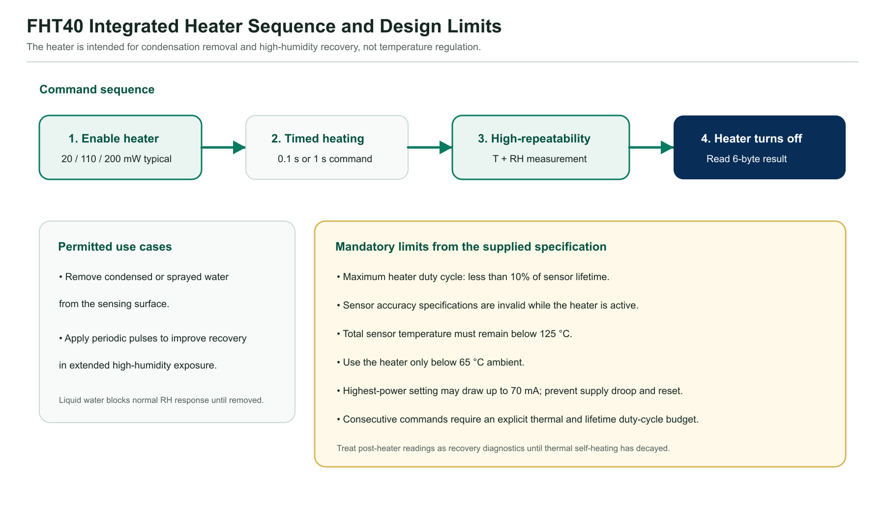
| 0x39 / 0x32 | 200 mW heater for 1 s / 0.1 s | 6 | High-repeatability result after heating. |
| 0x2F / 0x24 | 110 mW heater for 1 s / 0.1 s | 6 | Typical power at VDD = 3.3 V. |
| 0x1E / 0x15 | 20 mW heater for 1 s / 0.1 s | 6 | Respect heater duty-cycle and ambient limits. |
Temperature: T = -45 + 175 × ST / 65535 °C
Temperature: T = -49 + 315 × ST / 65535 °F
The RH equation can produce values below 0 %RH or above 100 %RH. Retain uncropped values only for diagnostic analysis; crop ordinary reported RH to 0 %RH through 100 %RH.
Reset paths
- Soft reset: send command 0x94.
- I²C general-call reset: send 0x06 to address 0x00; this affects every compatible device on the bus.
- Power cycle: power down while pulling SCL and SDA LOW as described in the supplied specification.
- Abort: an active sensor command can be aborted by soft reset or I²C general-call reset.
Integrated Heater Operation and Reliability Limits
Typical Application Circuit, PCB Placement and Exposure Control
- Separate from heat sources: keep the sensor away from regulators, processors, displays, batteries and high-current copper.
- Expose it to representative air: prevent stagnant pockets and isolate the sensing opening from board coatings, adhesives and enclosure walls.
- Protect during assembly: use an ESD-protected area and do not contaminate the sensing surface with flux, solvent or cleaning residue.
- Control I²C edges: choose pull-ups from bus capacitance and timing rather than copying one resistor value across all boards.
- Budget heater current: local supply impedance must not allow the highest-power pulse to reset the sensor or disturb other circuitry.
- Validate condensation recovery: test the complete vent, membrane, airflow path and heater duty cycle under the intended environmental profile.
DFN-4 Package, Land Pattern, Tape-and-Reel and Ordering
Package dimensions
| Symbol | Description | Minimum | Nominal / BSC / REF | Maximum | Unit |
|---|---|---|---|---|---|
| A | Overall height | 0.49 | 0.54 | 0.59 | mm |
| A1 | Standoff | 0 | 0.02 | 0.05 | mm |
| b | Terminal width | 0.25 | 0.30 | 0.35 | mm |
| b1 | Terminal feature | - | 0.21 REF | - | mm |
| c | Terminal thickness | - | 0.152 REF | - | mm |
| D / E | Body length / width | 1.45 | 1.50 | 1.55 | mm |
| D2 | Exposed-zone length | 0.90 | 1.00 | 1.10 | mm |
| E2 | Exposed-zone width | 0.30 | 0.40 | 0.50 | mm |
| e | Terminal pitch | - | 0.80 BSC | - | mm |
| K | Terminal-to-zone spacing | - | 0.25 REF | - | mm |
| L | Terminal length | 0.25 | 0.30 | 0.35 | mm |
| R | Corner radius | - | 0.10 REF | - | mm |
| ØS / ØS1 | Sensing-opening diameters | - | 0.60 / 0.50 BSC | - | mm |
| h1 | Opening-related height | - | 0.13 nominal | - | mm |
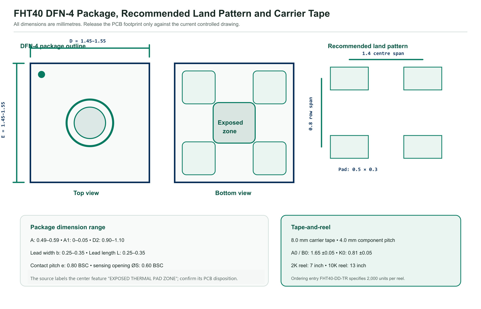
The recommended land pattern shows 1.4 mm centre span, 0.8 mm row span and 0.5 mm × 0.3 mm pads. Release the CAD footprint only against the controlled package drawing.
Ordering and handling
| Item | Specified value | Release note |
|---|---|---|
| Ordering code | FHT40-DD-TR | Standard FHT40, 7-bit address 0x44, tape-and-reel packing. |
| Package | DFN-4, 1.5 mm × 1.5 mm | Four peripheral contacts plus a central zone labelled “EXPOSED THERMAL PAD ZONE” in the source drawing; confirm its PCB disposition before footprint release. |
| Top marking | F40 + YWWD trace code | Verify the pin-1 laser mark and lot traceability during incoming inspection. |
| Standard packing quantity | 2,000 units | The ordering table specifies 2K; the carrier-tape page also describes a 10K, 13-inch reel option. |
| Moisture sensitivity | MSL 1 | The document states one-year storage under the recommended conditions. |
| Recommended storage | 10 °C to 50 °C; 20 %RH to 65 %RH | Keep components in their original packaging before use. |
Application Guidance and Design Limitations
The supplied specification lists automotive cabin, industrial control, smart home, consumer electronics and medical devices. These are application categories, not product- or system-level qualification claims.
 Automotive CabinCabin climate or comfort sensing only after component qualification, placement, condensation and EMC validation.
 Industrial ControlMonitor local air conditions with protection from corrosive gases, washdown, coating and hot equipment.
 Smart HomeUse in thermostats, ventilation and indoor monitors after enclosure airflow and self-heating tests.
 Consumer ElectronicsCompact low-power sensing for devices where display, battery and processor heat are isolated.
 Medical DevicesEnvironmental sensing only; no medical, diagnostic, life support or functional-safety qualification is stated.
FHT40 Engineering FAQs
What are the specified FHT40 humidity and temperature accuracies?
The supplied specification lists typical relative-humidity accuracy of ±1.8 %RH and typical temperature accuracy of ±0.2 °C. Maximum accuracy varies with humidity and temperature and must be checked against the specification curves.
What supply-voltage range does FHT40 support?
The electrical-characteristics table specifies 1.6 V to 5.5 V, with 3.3 V used as the typical test condition.
What I²C address and bus speed does FHT40 use?
The standard FHT40 ordering entry lists 7-bit address 0x44. The interface supports Standard-mode, Fast-mode and Fast-mode Plus operation up to 1 MHz. The document mentions two configurable addresses but does not identify the alternate address or ordering method; confirm it before design release.
Does FHT40 use clock stretching?
No. If conversion is not complete when the host sends the read header, the sensor returns NACK. The host must wait for the selected measurement duration or implement a controlled retry.
How is FHT40 measurement data protected?
Each 16-bit temperature or humidity word is followed by an 8-bit CRC. The polynomial is 0x31, initialization is 0xFF, reflection is disabled and final XOR is 0x00.
How are the raw FHT40 values converted?
Temperature in degrees Celsius is -45 + 175 × ST / 65535. Relative humidity is -6 + 125 × SRH / 65535 %RH. For ordinary reporting, crop calculated humidity to 0 %RH through 100 %RH.
When should the integrated heater be used?
The heater can help remove condensed water and improve recovery after extended high-humidity exposure. Use it as a controlled recovery function; sensor accuracy specifications do not apply while it is active.
What heater limits must be respected?
Keep total heater duty cycle below 10%, operate it only below 65 °C ambient, keep total sensor temperature below 125 °C and design the supply for up to 70 mA at the highest heater setting.
What external components are required?
The typical circuit shows a 100 nF bypass capacitor at VDD/VSS and 10 kΩ pull-ups on SDA and SCL. Final pull-up values must satisfy the actual bus voltage, capacitance, rise time, VOL and host current limits.
What package and ordering code are specified?
FHT40 uses a 1.5 mm × 1.5 mm DFN-4 package. The ordering table lists FHT40-DD-TR, top marking F40, tape-and-reel packing and 2,000 units per reel.
Can FHT40 be exposed to solvents or cleaning chemicals?
Avoid close or prolonged exposure to volatile solvents and organic compounds such as acetone, isopropanol, ethanol and toluene. The document warns that these can cause irreversible humidity-reading shifts.
This page summarizes FHT40_datasheet.pdf, whose internal part number is FHT40, for component evaluation and engineering reference. It does not replace the complete controlled product specification. Confirm the current revision, ordering code, I²C address, accuracy curves, commands, timing, heater limits, chemical exposure, package tolerances, land pattern, assembly process and qualification requirements before production release.
