
FHTC3 Temperature & Humidity Sensor
NYFEA FHTC3 integrates calibrated relative-humidity and temperature sensing, CRC-protected digital output and an I²C interface in a reflow-solderable 2 mm × 2 mm DFN6 package. Normal and low-power measurement commands support battery-powered and space-constrained designs.
Product scope: the supplied performance table specifies 0 to 100 %RH and -45 °C to +130 °C. A description paragraph states an upper limit of +135 °C; this page uses +130 °C because that value is repeated in the performance and absolute-maximum tables.
This engineering selection page summarizes the supplied datasheet. Use the controlled specification for final limits, timing, assembly and production release.
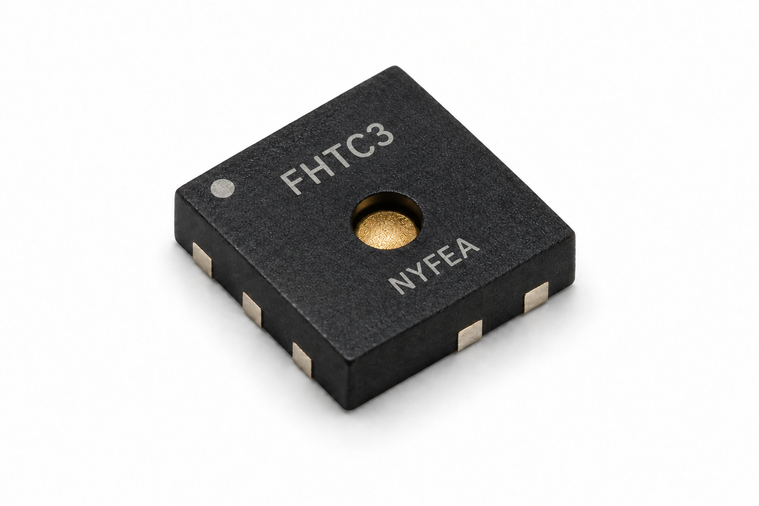
Product Overview and Selection Scope
FHTC3 is a factory-calibrated digital sensor for simultaneous temperature and relative-humidity measurement. Its low standby current, two measurement-power modes and small leadless package suit compact connected products.
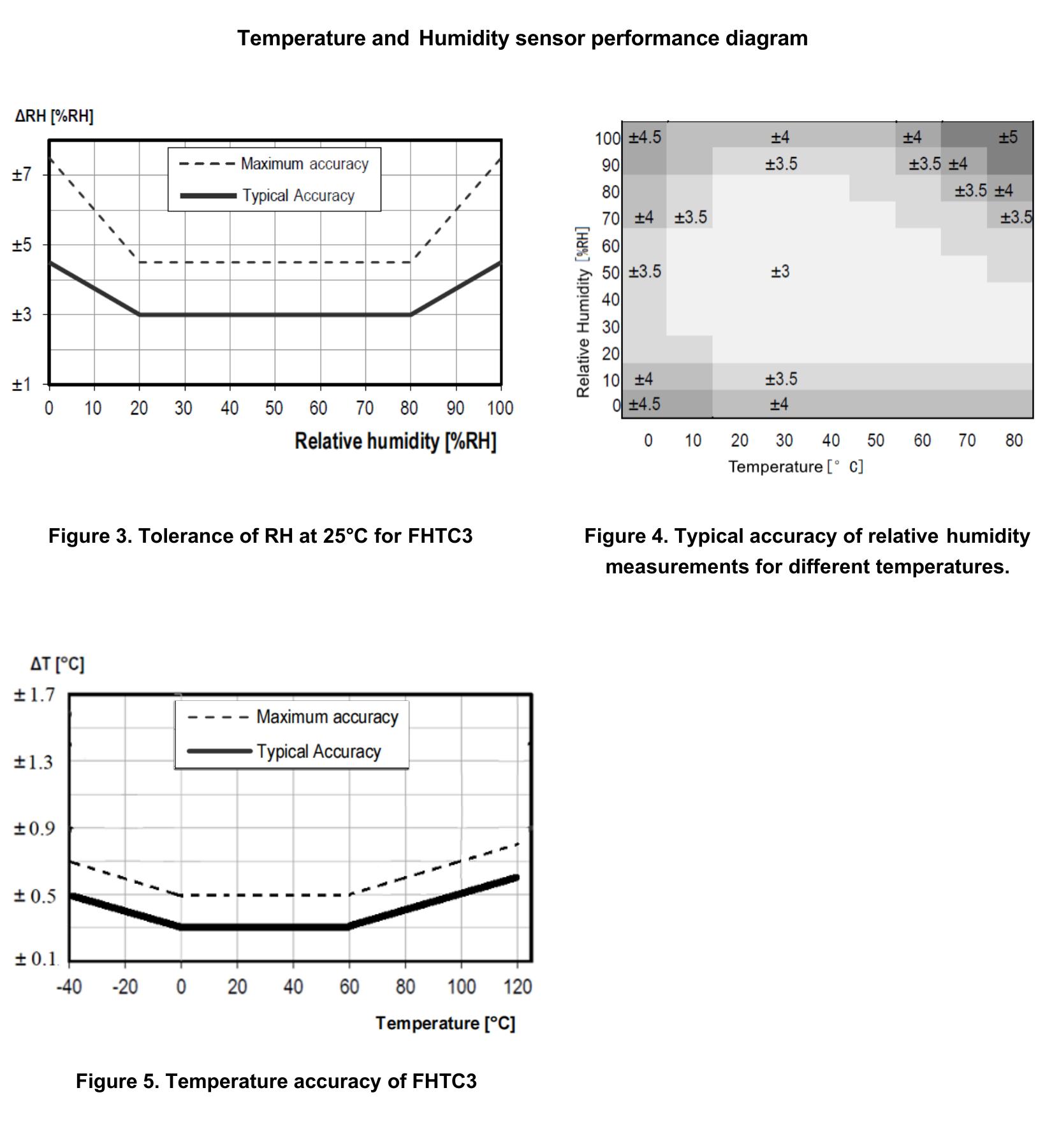
- Humidity measurement: 0 to 100 %RH range with typical ±3.0 %RH accuracy.
- Temperature measurement: -45 °C to +130 °C specified range with typical ±0.3 °C accuracy.
- Fine digital output: 0.01 %RH and 0.01 °C resolution entries in the performance table.
- Low power: 0.2 µA typical sleep current and 1 µA typical average current at one low-power measurement per second.
- Digital interface: I²C Normal, Fast and Fast Mode Plus operation with clock stretching.
- Wide supply: 1.6 V to 5.5 V operating supply range.
- Compact assembly: DFN6, 2 mm × 2 mm × 0.75 mm, reflow solderable and MSL1.
- Production ready: factory calibrated; tape-and-reel ordering with a dustproof breathable film.
Humidity and Temperature Performance
| Relative-humidity parameter | Minimum | Typical | Maximum | Unit / condition |
|---|---|---|---|---|
| Measurement range | 0 | - | 100 | %RH |
| Accuracy | - | ±3.0 | See performance curve | %RH at 25 °C |
| Resolution | - | 0.01 | - | %RH |
| Hysteresis | - | ±1.0 | - | %RH |
| Response time, t63 | - | 8 | - | s |
| Long-term drift | - | <0.5 | - | %RH/year |
Temperature performance
| Temperature parameter | Minimum | Typical | Maximum | Unit / condition |
|---|---|---|---|---|
| Measurement range | -45 | - | +130 | °C |
| Accuracy | - | ±0.3 | See performance curve | °C |
| Resolution | - | 0.01 | - | °C |
| Hysteresis | - | ±1.0 | - | °C |
| Response time, t63 | - | <5–30 | - | s, as printed in source |
| Long-term drift | - | <0.02 | - | °C/year |
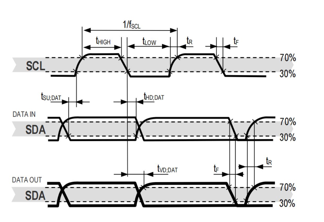
Electrical Characteristics and Interface Timing
Unless otherwise stated, the electrical entries below apply at 25 °C and VDD = 3.3 V.
| Parameter | Minimum | Typical | Maximum | Unit / condition |
|---|---|---|---|---|
| Supply voltage, VDD | 1.6 | 3.3 | 5.5 | V |
| Power-on reset threshold, VPOR | 1.3 | 1.4 | 1.5 | V |
| Idle current | - | 45 | 80 | µA |
| Sleep current | - | 0.2 | 0.3 | µA |
| Measurement current, normal mode | - | 500 | 860 | µA |
| Measurement current, low-power mode | - | 320 | 620 | µA |
| Average current, normal mode | - | 3 | - | µA at 1 measurement/s |
| Average current, low-power mode | - | 1 | - | µA at 1 measurement/s |
| Input LOW, VIL | - | - | 0.4 × VDD | V |
| Input HIGH, VIH | 0.7 × VDD | - | - | V |
| Output LOW, VOL | - | - | 0.2 × VDD | V at 3 mA sink |
System timing
| Operation | Typical | Maximum | Unit |
|---|---|---|---|
| Power-up time | 180 | 500 | µs |
| Soft-reset time | 180 | 500 | µs |
| Measurement duration, normal mode | 10 | 11 | ms |
| Measurement duration, low-power mode | 1.5 | 2 | ms |
Absolute maximum ratings
| Stress | Limit |
|---|---|
| Supply voltage | -0.3 V to +6 V |
| Operating and storage temperature | -45 °C to +130 °C |
| ESD, human-body model | -4 kV to +4 kV |
| ESD, charged-device model | -500 V to +500 V |
| Latch-up current at 125 °C | ±100 mA |
Pin Assignment and Application Circuit
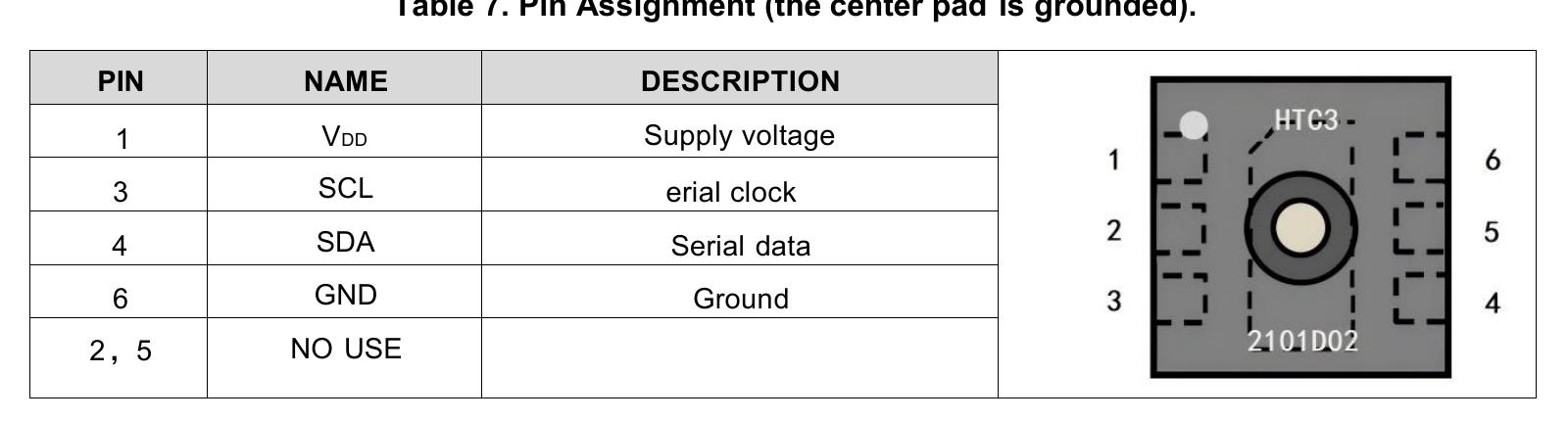
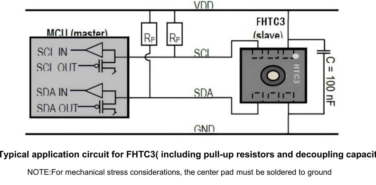
| Pin | Name | Function | Design guidance |
|---|---|---|---|
| 1 | VDD | Supply voltage | Place a 100 nF decoupling capacitor close to the sensor. |
| 2 | NC | No use | Leave unconnected as directed by the controlled datasheet. |
| 3 | SCL | I²C serial clock | Use an external pullup sized for supply voltage, capacitance and required timing. |
| 4 | SDA | I²C serial data | Use an external pullup and route away from noise sources. |
| 5 | NC | No use | Leave unconnected as directed by the controlled datasheet. |
| 6 | GND | Ground | Provide a low-impedance return. |
| Center pad | GND | Exposed pad | Solder to ground; the datasheet identifies this as necessary for mechanical-stress control. |
I²C Interface and Measurement Flow
FHTC3 uses the fixed 7-bit I²C address 0x70. It supports Normal, Fast and Fast Mode Plus operation up to 1 MHz and can hold SCL LOW with clock stretching while a measurement is in progress.
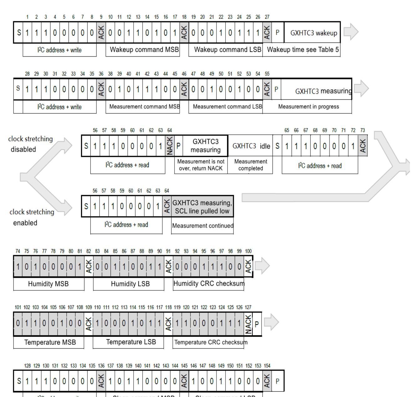
- Wake first: send command 0x3517 before measurement or register access.
- Select order: command options return temperature first or relative humidity first.
- Select power mode: normal mode takes about 10 ms; low-power mode takes about 1.5 ms typically.
- Clock stretching: when enabled, the device can acknowledge a read and hold SCL LOW until data is ready.
- Polling without stretching: an attempted read typically receives NACK while conversion is still running.
- Sleep after use: send 0xB098 to minimize average current.
Measurement readout
The device returns two bytes for the first selected quantity, one CRC byte, two bytes for the second quantity and a second CRC byte. The host acknowledges each byte it wants to continue reading and can terminate the transaction with NACK.
Measurement and System Commands
Measurement command matrix
| Power mode | Clock stretching | First value | Command |
|---|---|---|---|
| Normal | Enabled | Temperature | 0x7CA2 |
| Normal | Enabled | Relative humidity | 0x5C24 |
| Normal | Disabled | Temperature | 0x7866 |
| Normal | Disabled | Relative humidity | 0x58E0 |
| Low power | Enabled | Temperature | 0x6458 |
| Low power | Enabled | Relative humidity | 0x44DE |
| Low power | Disabled | Temperature | 0x609C |
| Low power | Disabled | Relative humidity | 0x401A |
System commands
| Function | Command | Use | Engineering note |
|---|---|---|---|
| Wake | 0x3517 | Exit sleep before communicating. | Allow the specified wake timing before the next operation. |
| Sleep | 0xB098 | Enter the lowest-current state. | Use after readout where duty-cycled operation is required. |
| Soft reset | 0x805D | Reset the addressed device state. | Typical execution time is 180 µs; maximum is 500 µs. |
| General-call reset | Address 0x00, data 0x06 | Reset all compatible devices that accept I²C general call. | Confirm other slaves on the bus before using this command. |
| Read ID | 0xEFC8 | Read the 16-bit device ID and CRC. | Check the returned CRC before accepting the identity. |
CRC Verification and Raw-Data Conversion
Every 16-bit humidity, temperature or ID word is followed by a CRC-8 byte. Calculate the CRC over the two preceding data bytes and reject or retry data when the result does not match.
Initialization: 0xFF · Reflect input/output: false · Check value: CRC(0xBEEF) = 0x92
Conversion formulas
Temperature: T (°C) = -45 + 175 × ST / 216
SRH and ST are unsigned 16-bit raw values assembled most-significant byte first from the I²C response.
DFN6 Package, Land Pattern and Ordering
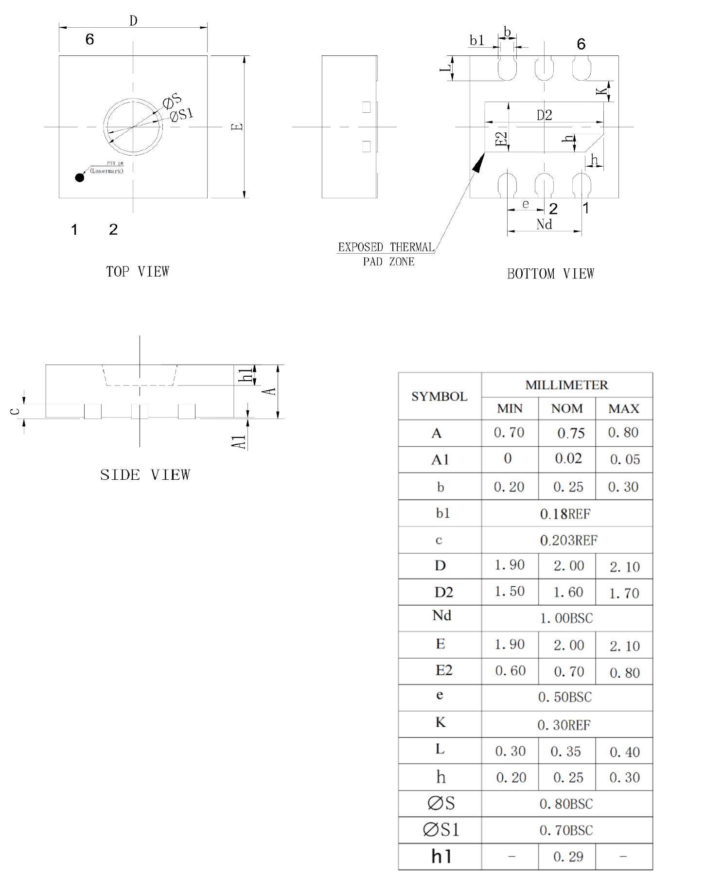
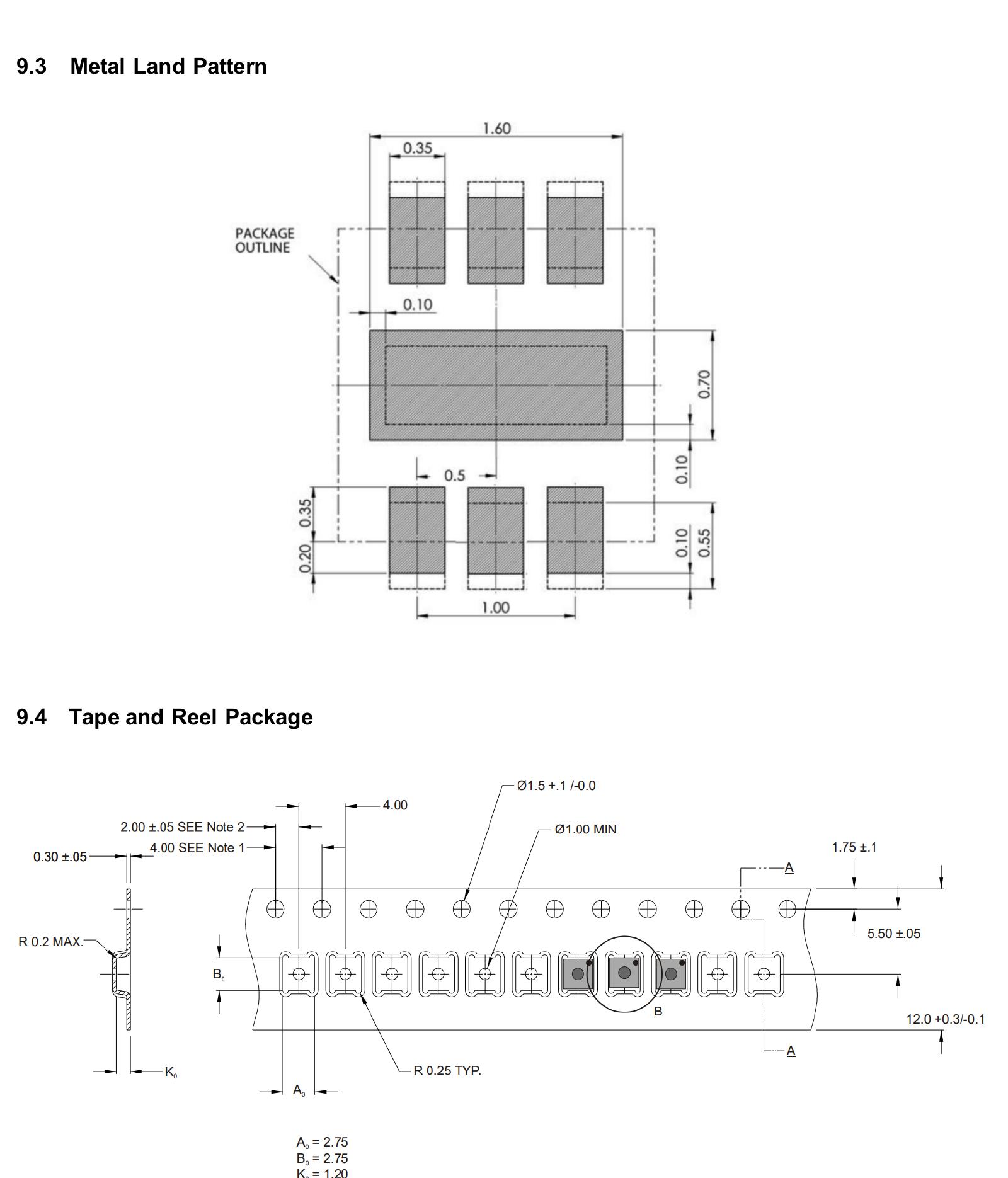
| Dimension | Minimum | Nominal | Maximum | Unit |
|---|---|---|---|---|
| Body width, D | 1.90 | 2.00 | 2.10 | mm |
| Body length, E | 1.90 | 2.00 | 2.10 | mm |
| Overall height, A | 0.70 | 0.75 | 0.80 | mm |
| Lead pitch, e | 0.50 basic | mm | ||
| Lead width, b | 0.20 | 0.25 | 0.30 | mm |
| Lead length, L | 0.30 | 0.35 | 0.40 | mm |
| Sensing aperture, ØS | 0.80 basic | mm | ||
| Inner aperture, ØS1 | 0.70 basic | mm | ||
Ordering information
| Order code | Device | Package | Standard packing quantity | Packing |
|---|---|---|---|---|
| FHTC3-TR | FHTC3 | DFN6, 2 mm × 2 mm | 2,000 | Tape and reel, dustproof breathable film |
The package is identified as moisture-sensitivity level MSL1. Follow the controlled reflow, stencil, land-pattern and handling requirements for production.
Quality, Storage and Chemical Handling
- Keep the film intact: do not tear or contaminate the dustproof breathable film over the sensing aperture.
- Avoid volatile chemicals: the source specifically lists substances including acetone, methyl ethyl ketone, isopropanol, ethanol and toluene.
- Avoid aggressive media: bases above pH 9, hydrogen peroxide, ammonia and corrosive gases can damage or shift the sensor.
- Control coating processes: prevent conformal coating, adhesive, flux and cleaning agents from reaching the sensing surface.
- Recover from extreme humidity: prolonged high-humidity exposure can create a temporary offset; use the source conditioning guidance.
- Protect against condensation: liquid water and residue can block diffusion and change response time or accuracy.
Application Areas
The supplied datasheet identifies consumer electronics, cold-chain transportation, smart homes, smart agriculture, communication equipment and photovoltaic energy storage.
 Consumer ElectronicsCompact environmental sensing for connected and battery-powered devices.
 Cold-Chain TransportHumidity and temperature logging after placement and response-time validation.
 Smart HomeRoom monitoring, comfort control and connected appliance sensing.
 Smart AgricultureGreenhouse and growing-environment monitoring with contamination protection.
 Communication EquipmentEnvironmental monitoring inside cabinets, radios and network infrastructure.
 PV Energy StorageCabinet and enclosure monitoring after thermal-gradient and EMC testing.
FHTC3 Engineering FAQs
What humidity and temperature accuracy does FHTC3 specify?
The performance table lists typical accuracy of ±3.0 %RH and ±0.3 °C. Review the performance curves and complete operating conditions when setting a system error budget.
What measurement ranges should be used in a design?
Use 0 to 100 %RH and -45 °C to +130 °C. Although one description paragraph states +135 °C, both the performance and absolute-maximum tables state +130 °C.
What are the supply and I²C limits?
The supply range is 1.6 V to 5.5 V. The fixed 7-bit address is 0x70, and the interface supports I²C operation up to 1 MHz under the corresponding timing limits.
How low is the operating current?
Typical sleep current is 0.2 µA. At one measurement per second, the datasheet lists typical average current of 3 µA in normal mode and 1 µA in low-power mode.
How long does a measurement take?
The system-timing table lists 10 ms typical and 11 ms maximum in normal mode, or 1.5 ms typical and 2 ms maximum in low-power mode.
How are humidity and temperature read?
Wake the device, send the required measurement command, wait or use clock stretching, then read two data bytes plus CRC for each quantity. Send the sleep command after readout for minimum power.
How should the host verify data?
Calculate CRC-8 with polynomial 0x31 and initialization 0xFF over each two-byte word. The supplied check example gives CRC(0xBEEF) = 0x92.
Does the exposed center pad need to be connected?
Yes. The pin-assignment section identifies the center pad as grounded and instructs that it be soldered to ground for mechanical-stress control.
What package and ordering code are specified?
FHTC3 is supplied in a 2 mm × 2 mm × 0.75 mm DFN6 package. The listed tape-and-reel ordering code is FHTC3-TR, with a standard packing quantity of 2,000.
What materials must be kept away from the sensor?
Keep solvents, volatile organic compounds, high-pH bases, hydrogen peroxide, ammonia, corrosive gases, conformal coating, adhesive and cleaning residue away from the sensing aperture.
This page summarizes the supplied “FHTC3_datasheet .pdf” for component evaluation and engineering reference. It does not replace the complete controlled datasheet. Confirm the current revision, guaranteed performance, interface timing, command sequence, package tolerances, reflow process, chemical compatibility and qualification requirements before production release.
