MFRC522 Not Detecting Cards Reliably? Hardware Checks and an NF522 Evaluation Path
A board-level guide to separating MFRC522 communication, power, tag-protocol and RF faults—and deciding when an NF522 evaluation makes engineering sense.
DIRECT ANSWER
An MFRC522-based reader that communicates over SPI but does not detect cards is not necessarily suffering from a failed reader IC. Separate host-interface, power/reset, RF-field, antenna and tag-compatibility checks before changing hardware. NF522 can be evaluated for a new or redesigned 13.56 MHz reader, but “direct replacement” is an engineering result—not a keyword. Confirm the footprint and pins, supply rails, host-bus transactions, register behavior, firmware, RF matching and card-set performance before approving any migration.
Searches for “MFRC522 not detecting card,” “MFRC522 firmware version 0x0” and “MFRC522 replacement” often describe different failures. One is a digital communication problem. Another is an RF or tag-compatibility problem. A third is a product-lifecycle decision. Treating all three as “replace the chip” wastes debug time and can carry an unverified prototype into production.
This guide first diagnoses the existing MFRC522 design. It then shows when NF522 is relevant and what must be revalidated. The objective is a repeatable engineering decision, not an unsupported claim that similarly named reader ICs are interchangeable.
1. MFRC522 IC or RC522 module: identify what you are debugging
MFRC522 is a 13.56 MHz contactless reader/writer IC. The inexpensive boards commonly called “RC522 modules” add a PCB antenna, matching and filtering components, crystal, decoupling, connectors and sometimes board-level power circuitry. A module symptom therefore does not identify the IC as the root cause.
Record these facts before opening the firmware
- The exact IC or module marking and the schematic revision.
- The MCU, supply voltage, logic voltage and selected SPI, I²C or UART interface.
- The credential frequency and air-interface protocol.
- The antenna and matching-network BOM, PCB revision and enclosure state.
- Whether the fault occurs at cold start, after sleep, only in the enclosure or only with particular cards.
Why this matters: replacing a breakout module is a board-level decision. Replacing a bare reader IC is a schematic, PCB, firmware and RF decision.
2. Use the symptom to choose the first measurement
Do not begin by swapping random capacitors or increasing transmit strength. Classify the failure at the lowest layer that has not yet been proved.
| Observed symptom | Most likely layer | First useful check |
|---|---|---|
| Version or register reads remain 0x00 | Power, reset, interface selection, held-low MISO or wiring | Measure the IC rails and reset at the pins; capture CS, SCK, MOSI and MISO. |
| Reads remain 0xFF | Open or inactive bus, missing chip select, reset or pin-direction error | Confirm continuity, CS timing and that no shared peripheral owns MISO. |
| Register reads change between identical transactions | SPI timing, edge integrity, clock, power or grounding | Lower SCK, shorten wiring and compare the decoded bytes with the waveform. |
| Registers are stable, but every poll times out | Command/FIFO/IRQ, RF path, antenna, receiver or wrong protocol | Trace one complete transaction and confirm a field at the antenna. |
| One credential works and another does not | Frequency, protocol, card size/orientation or coupling | Identify each credential; test a controlled, known-good 13.56 MHz Type A card. |
| Open-board tests pass, assembled product fails | Metal detuning, cable noise, display/battery coupling or enclosure spacing | Compare antenna impedance and read-zone maps open versus assembled. |
| One reader works, multiple readers fail | Chip-select handling, shared MISO, power transients or RF interaction | Disable all but one reader, then add devices while monitoring bus release and supply current. |
3. Why MFRC522 reports Firmware Version 0x0 or 0xFF
For the NXP MFRC522, VersionReg is at address 37h; documented version values include 91h for version 1.0 and 92h for version 2.0. A persistent 00h or FFh usually means the host has not yet established a valid register transaction. It does not prove an antenna fault, and it does not by itself prove a damaged IC.
- Measure before interpreting: verify the reader supplies and reset level at the package or module, not only at the regulator.
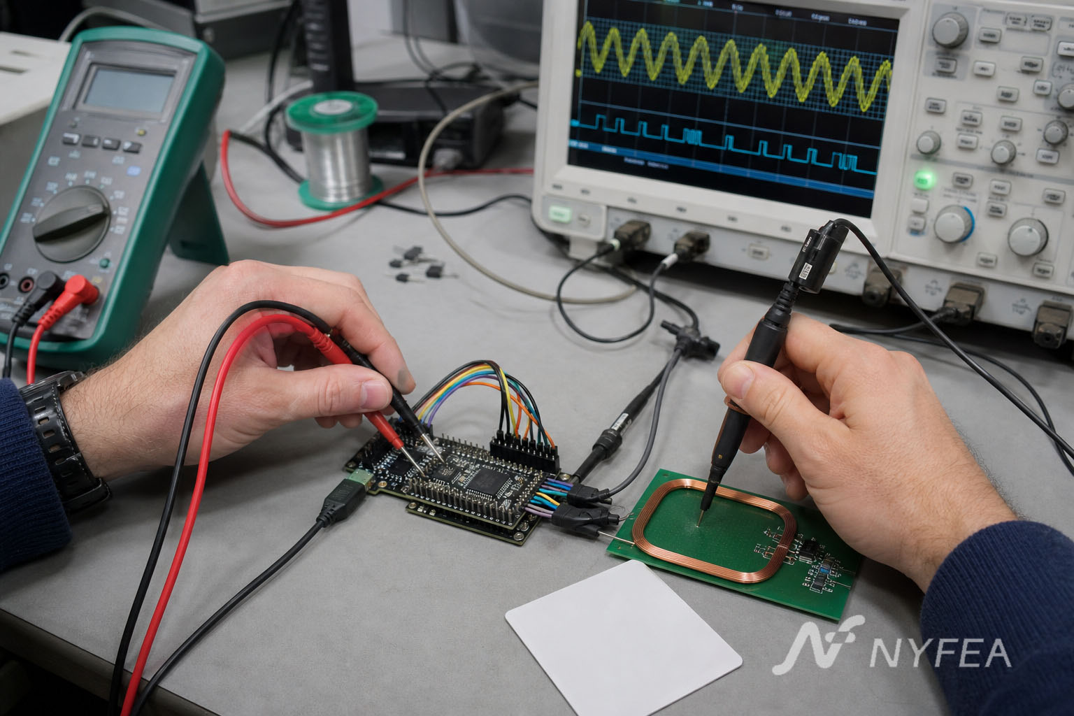
- Capture a complete SPI access: check chip-select boundaries, clock polarity and phase, bit order and the address/read-write framing used by the driver.
- Remove bus ambiguity: disconnect or tri-state other MISO devices and test with shorter conductors.
- Repeat the read: a single plausible value is not enough; the same controlled transaction must be repeatable across reset and cold start.
Voltage caution: the bare MFRC522 is not a generic 5 V device. NXP specifies its principal analog, digital and transmitter supplies in the 2.5–3.6 V range, with separate requirements for the interface supply. A breakout board’s connector label does not establish that every signal is 5 V tolerant. Check the actual module schematic and the MCU logic levels.
4. SPI communication does not prove the RF link
Stable register access proves the host digital path. Card detection additionally requires a valid transceive sequence, correct FIFO and interrupt handling, an active 13.56 MHz field, a tuned antenna, a usable receive path and a card using a supported protocol.
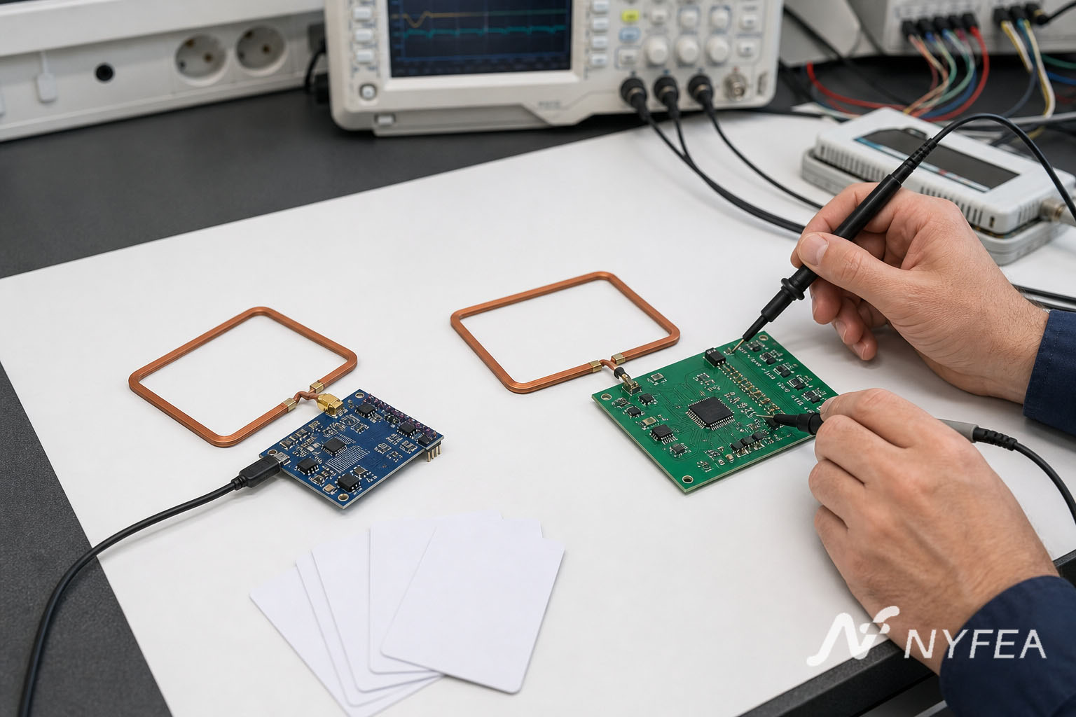
When SPI passes but no card answers, capture one polling transaction rather than repeatedly restarting the complete application. Record the command start, timer outcome, interrupt status, error status and FIFO length. In parallel, use a small near-field probe to confirm that the antenna—not merely TX1/TX2—produces a field.
- A waveform at the transmitter pins does not establish current through the loop antenna.
- A clean carrier does not establish receiver sensitivity or correct modulation settings.
- An empty FIFO after timeout does not identify firmware or RF as the cause without interrupt and error context.
- A successful UID read once does not establish reliable operation across position, orientation, enclosure and production tolerance.
5. Confirm the card frequency and protocol before changing the reader
MFRC522 is specified for ISO/IEC 14443 Type A, MIFARE and NTAG communication. It is not a 125 kHz reader, and its official feature set does not include ISO/IEC 14443 Type B or ISO/IEC 15693 reader modes. Two key fobs that look identical may therefore require different readers.
Start with a documented Type A credential placed parallel to and centered over the antenna. If that card works, expand to the approved card set one technology at a time. If the product requirement includes Type B or ISO/IEC 15693, the issue is no longer only troubleshooting: it is also reader-IC selection.
6. Why read range changes after PCB and enclosure integration
NXP describes MFRC522 read distance as antenna- and tuning-dependent; the often-repeated “up to 50 mm” figure is not a system guarantee. The same principle applies to NF522. Reader IC, antenna geometry, matching components, supply voltage, card antenna, metal, ferrite, display noise and enclosure spacing form one RF system.
Compare the same reader in three controlled states
- Open PCB: production PCB and antenna, no enclosure.
- Mechanically assembled: final spacing, metal, ferrite and plastics installed.
- Electrically active product: display, DC/DC converters, motors, cables and radios operating in worst-case modes.
For each state, log supply voltage, field-on current, antenna response and a position/orientation read map using the same credentials. A shorter assembled read range is evidence of system loading or interference—not automatically evidence that the reader IC is defective.
7. Platform-specific failures still belong to the same layers
Arduino prototype to ESP32
A working Arduino example does not validate an ESP32 pin map, boot-strapping pins, SPI host selection, task timing or logic-level arrangement. First reproduce stable register reads with a minimal transaction, then add the full library and application.
Raspberry Pi
Confirm that the intended SPI controller and chip-select device are enabled and accessible. When multiple readers share a bus, give each reader an independent chip select and verify that every inactive device releases MISO.
STM32 or another production MCU
Port the bus transaction and reset sequence before porting the complete application. Compare captured bytes with the reader data sheet, then add interrupt-driven operation, timeouts and recovery. A library compiling successfully is not proof that its electrical interface and transaction framing match the board.
8. When troubleshooting becomes a new-design decision
If the existing MFRC522 design meets its protocol, power, supply and lifecycle requirements, a measured fix may be lower risk than changing the reader. An evaluation of another IC becomes more rational when the product needs broader protocol coverage, a defined low-power card-detection strategy, a controlled custom PCB, a refreshed supply plan or a new long-term design baseline.
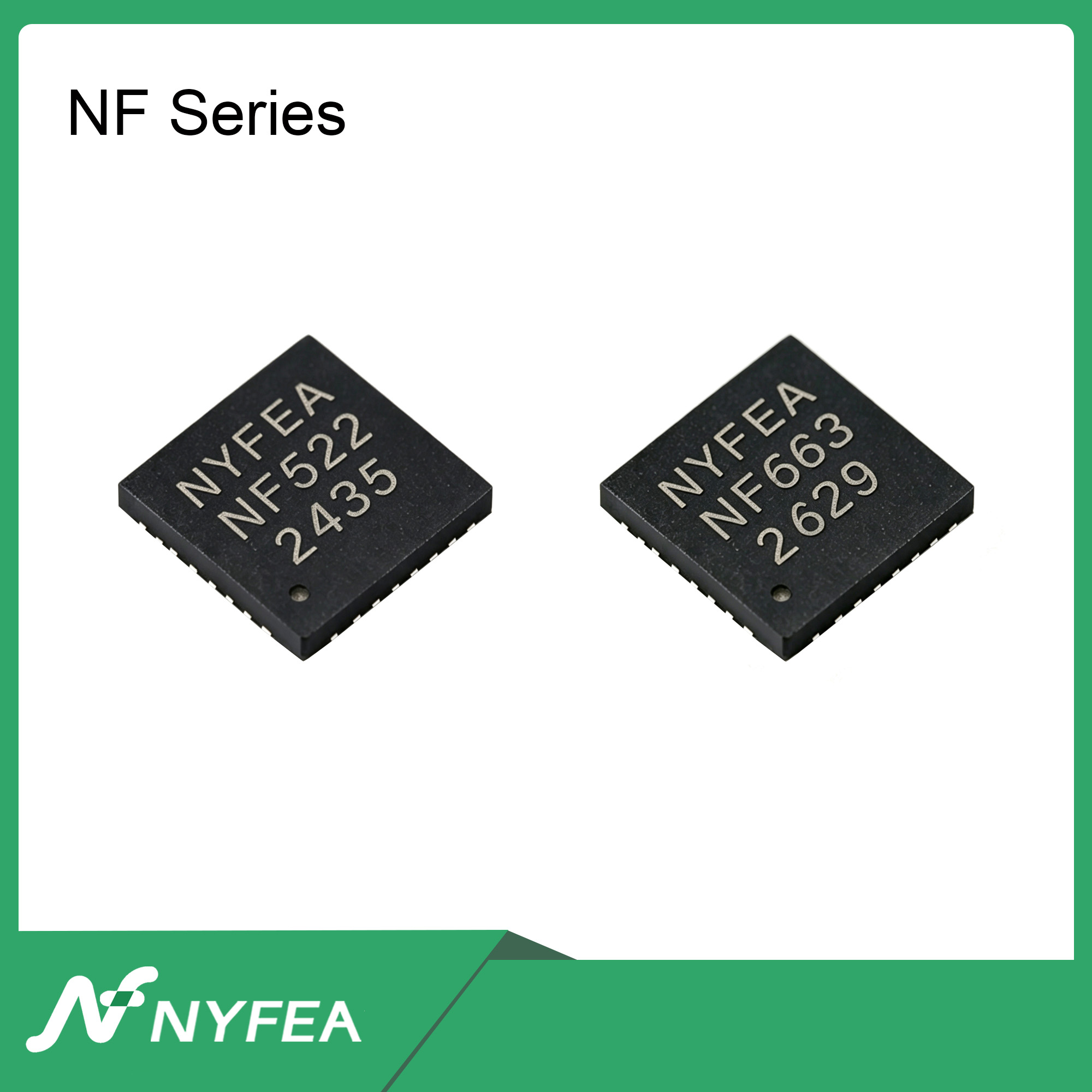
Lifecycle context: as checked on August 15, 2026, NXP marks ordering code MFRC52202HN1 “End of Life” and not recommended for new designs; NXP names CLRC663 plus as its recommended new-design product. NF522 is a separate NYFEA product and an independent engineering candidate. It is not an NXP-endorsed alternative.
9. NF522 vs MFRC522: relevant design facts, not a drop-in claim
| Design question | MFRC522 documented baseline | NF522 documented baseline | Migration meaning |
|---|---|---|---|
| Carrier frequency | 13.56 MHz | 13.56 MHz | The same frequency does not establish antenna, pin or firmware compatibility. |
| Reader protocols | ISO/IEC 14443 Type A, MIFARE and NTAG | ISO/IEC 14443 Type A, Type B and ISO/IEC 15693 reader modes; M1 mode | NF522 can be evaluated where broader protocol coverage is required; validate the actual cards and software flow. |
| Type A data rates | 106, 212, 424 and 848 kBd | 106, 212, 424 and 848 kbit/s | Matching headline rates do not prove matching register configuration or timing behavior. |
| Host interfaces | SPI, I²C and serial UART | SPI, I²C and UART | Validate transaction framing, modes, address selection, timing, reset and I/O levels. |
| Maximum documented SPI rate | 10 Mbit/s | 12 Mbit/s | Choose a rate proven on the target MCU, routing and firmware; maximum figures are not a migration setting. |
| FIFO | 64-byte shared transmit/receive FIFO | 64-byte transmit/receive FIFO | Revalidate FIFO commands, status, errors and interrupt handling. |
| Reference clock | 27.12 MHz crystal connection | External 27.12 MHz crystal | Recheck oscillator network, startup and layout against the selected device data sheet. |
| Package description | HVQFN32, 5 × 5 mm | QFN32 | A similar pin count is not proof of the same footprint, exposed pad or pin assignment. |
| Operating temperature | −25°C to +85°C ambient | −25°C to +85°C ambient | System qualification is still required across the final power and RF conditions. |
Comparison boundary: values above come from the controlled MFRC522 and NF522 technical documents available during this review. Confirm the latest ordering code, document revision and application requirements before design approval. Read-distance numbers are intentionally excluded because they are not comparable without the same antenna, card, enclosure and test method.
10. Can NF522 directly replace MFRC522?
Not on model names or headline parameters alone. NF522 may be evaluated as an alternative for a new or redesigned 13.56 MHz reader, especially when Type B or ISO/IEC 15693 reader modes are required in addition to Type A. However, the current NF522 data sheet does not state MFRC522 pin-to-pin, footprint, register-map, firmware or antenna-network compatibility.
A defensible answer requires the following sequence:
- Freeze the MFRC522 baseline: save the schematic, PCB, antenna dimensions, BOM, firmware revision, card set and measured read-zone results.
- Compare the package and every pin: include exposed pad, power and ground pins, TX/RX, clock, reset, IRQ and interface-selection pins.
- Compare all power domains: check operating ranges, sequencing, I/O thresholds, decoupling and field-on current—not only the label “3.3 V.”
- Audit host transactions: verify SPI framing/mode, I²C address and timing or UART startup behavior with a logic analyzer.
- Port by function, not by assumption: validate reset values, command flow, FIFO, timer, CRC, interrupt and error handling against NF522 documentation.
- Retune the RF system: keep the old antenna geometry only as a starting point; measure the matching network on the NF522 PCB in the final enclosure.
- Run an A/B qualification: compare cold start, sleep/wake, card detection, read zone, noise immunity, temperature and recovery using the same production-intent test plan.
11. What can be reused, and what must be revalidated?
| Potentially reusable engineering asset | Mandatory revalidation |
|---|---|
| Product requirements and supported-card list | NF522 protocol configuration and end-to-end card transactions |
| Position/orientation read-zone test fixture | Pass limits using the NF522 board and final enclosure |
| Antenna outline as an initial geometry | EMC filter, matching values, impedance, field strength and receive margin |
| Host-side application states and error policy | Driver, register accesses, commands, IRQ, timer, CRC and FIFO behavior |
| Manufacturing traceability and test concept | NF522-specific test points, diagnostics, limits and golden-board references |
12. A production-oriented acceptance test
- Cold-start and reset recovery are repeatable
- Register identification and bus transactions are stable
- Required Type A, Type B and/or ISO/IEC 15693 cards pass
- Timeout, card removal and error recovery do not require a power cycle
- Read-zone coverage meets the product requirement in the enclosure
- Display, converter, cable and radio noise are active during RF tests
- Low-power entry, wake source and wake latency are measured at system level
- Production component tolerances and antenna variation are represented
- Temperature and supply corners use documented pass criteria
- Firmware and hardware revisions are traceable in every result
Do not approve an MFRC522-to-NF522 migration because one card produces one UID on an open bench. Approve it when the NF522 design passes the same controlled product requirements with a documented margin.
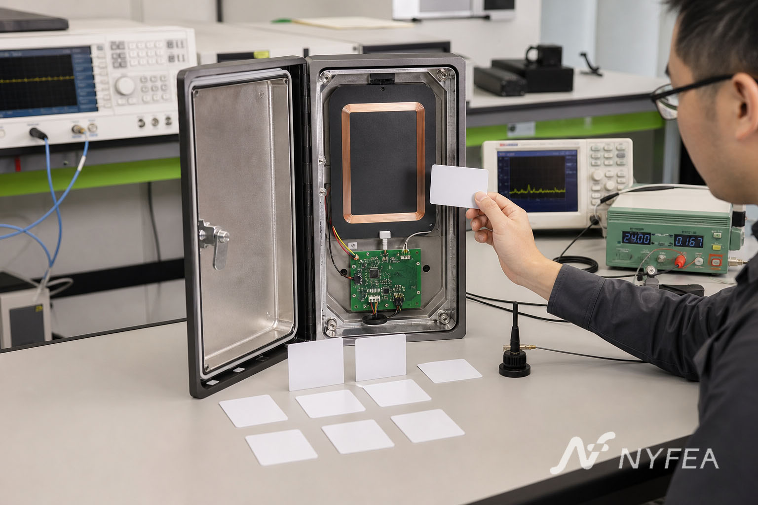
Engineering FAQs
Why does MFRC522 show Firmware Version 0x0?
A persistent 0x00 usually means the MCU has not completed a valid register read. Check power, reset, interface selection, CS, SPI mode and MISO before debugging the antenna. A 0xFF result often points to an open or inactive bus, but the waveform and board measurements must decide the cause.
Why does MFRC522 communicate over SPI but not detect a card?
SPI proves only the host digital path. Card detection also needs a valid command and FIFO/interrupt flow, an active 13.56 MHz RF field, a matched antenna, a working receiver and a card using a supported protocol.
Why does MFRC522 work with Arduino but not ESP32?
The MCU change can alter pin mapping, boot-pin behavior, SPI controller selection, clock rate, timing and logic levels. Prove repeatable register reads with a minimal ESP32 transaction before adding the complete library and application.
Can MFRC522 read 125 kHz RFID tags?
No. MFRC522 is a 13.56 MHz reader IC. A 125 kHz tag requires a reader designed for that frequency and air interface.
Why can MFRC522 read one card but not another?
The credentials may use different frequencies or protocols, and their antenna size and orientation also change coupling. MFRC522 officially supports ISO/IEC 14443 Type A, MIFARE and NTAG; it does not provide Type B or ISO/IEC 15693 reader modes.
How can I improve MFRC522 read reliability?
Stabilize power and reset, prove the host bus, identify the card protocol, inspect the matching network and antenna, then map read performance in the final enclosure with all noise sources active. Do not optimize from a single open-board read.
Can multiple MFRC522 readers share one SPI bus?
They can share clock and data lines when each reader has controlled chip select and every inactive device releases MISO. Also check power transients, wiring length and RF interaction between simultaneously active antennas.
Is NF522 a direct replacement for MFRC522?
Do not assume so. NF522 is an independent 13.56 MHz reader IC that can be evaluated for a new or redesigned product, but direct replacement requires verified package and pin mapping, power, host transactions, registers, firmware, RF matching and final-system performance.
Download the NF522 technical data
Use the controlled NF522 document for pin functions, electrical conditions, protocols, commands and register behavior. This article is a migration and troubleshooting method; it does not replace either manufacturer’s current technical documentation.
Download NF522 Technical Datasheet (PDF)
Evaluating an MFRC522-based reader for a new design?
Share the required card protocols, host interface, supply plan, antenna dimensions, enclosure stack and measured MFRC522 baseline with NYFEA. The useful first question is not “Is it drop-in?” but “Which requirements and interfaces must the NF522 design prove?”
Trademark and relationship notice: MFRC522, MIFARE and NTAG are identifiers or marks associated with their respective owner. NF522 is a NYFEA product. NYFEA and NF522 are not affiliated with, endorsed by or sponsored by NXP. Company legal review should approve final trademark wording before publication.