CH58x · SHT40 · I²C DEVELOPMENT
CH58x I²C Guide: Hardware I²C, Software I²C and SHT40 Examples
To read an SHT40 from a CH58x controller, establish the 3.3 V I²C bus, send the one-byte 0xFD command, finish the write transaction, wait for conversion, read six bytes, check both CRC bytes, and only then convert temperature and humidity. SHT20 requires a separate command and timing path.
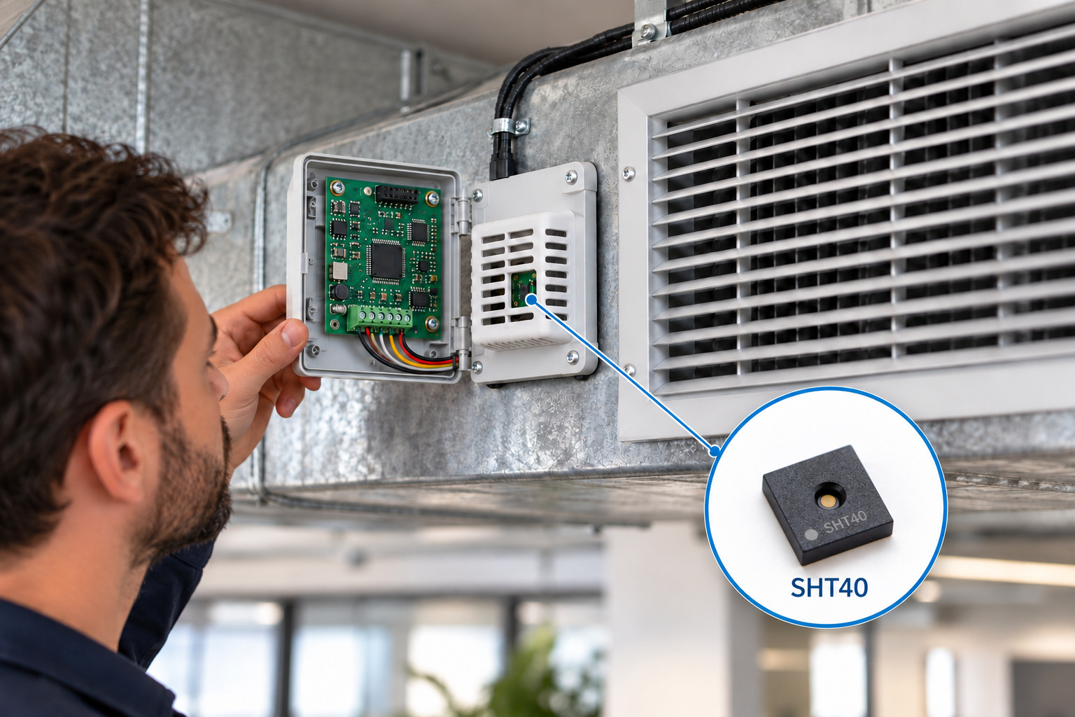
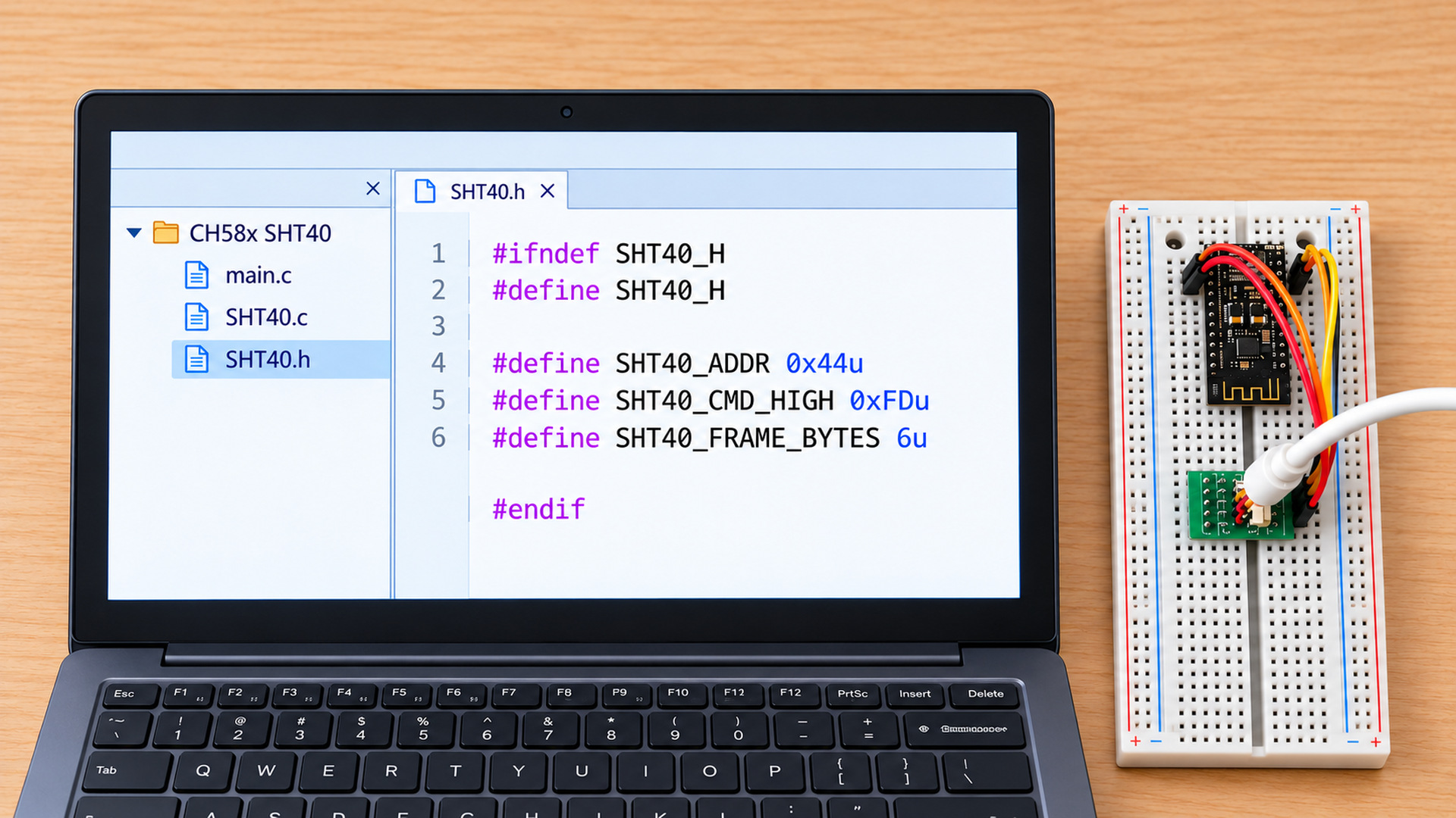
0x44 for the device discussed here. The source CH58x library example passes 0x88 to its address function because that call expects the left-shifted address. Check the installed EVT API before copying that value.1. Establish the electrical and firmware baseline
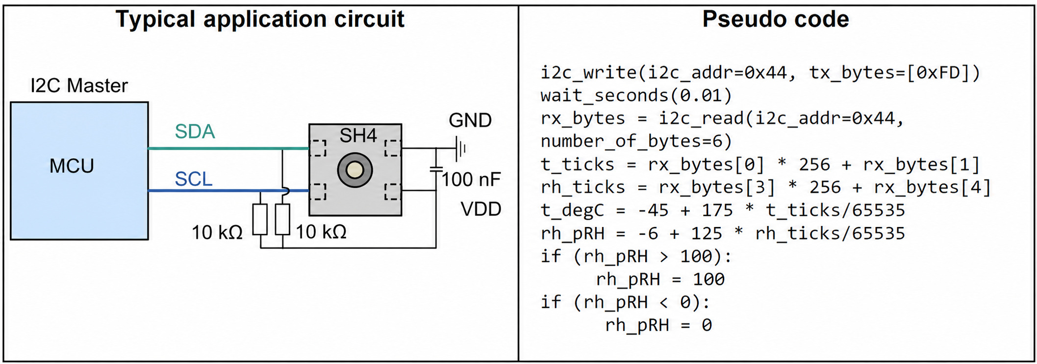
The SHT40 needs SDA and SCL pull-ups to the bus logic rail, a common ground, and a local supply capacitor. The typical circuit below shows 10 kΩ pull-ups and 100 nF decoupling; 10 kΩ is a reference-circuit value, not a guarantee at 400 kHz on a capacitive cable or a multi-board bus. Check total bus capacitance, effective pull-up resistance and rise time on the assembled board.
| Item | CH585 example / SHT40 requirement | Practical check |
|---|---|---|
| Power and logic | SHT40 VDD: 1.08–3.6 V; use pull-ups to the sensor-compatible logic rail. | Measure VDD and the idle SDA/SCL high level at the sensor, not only at the MCU. |
| Pins | The supplied CH585 example uses PB12/SDA and PB13/SCL; its remap path uses PB20/SDA and PB21/SCL. | Match the installed CH58x variant, board schematic and EVT pin-remap setting. |
| Address | SHT40: 0x44 as a 7-bit address; the source SDK example shifts it to 0x88 for one specific call. | Confirm whether your API accepts 7-bit or already-shifted addresses. |
| Bus rate | The source initializes 100 kHz; standard and fast modes have different rise-time budgets. | Start at 100 kHz, then inspect edges before increasing speed. |
/* CH585 source-project initialization path; confirm names in your EVT. */
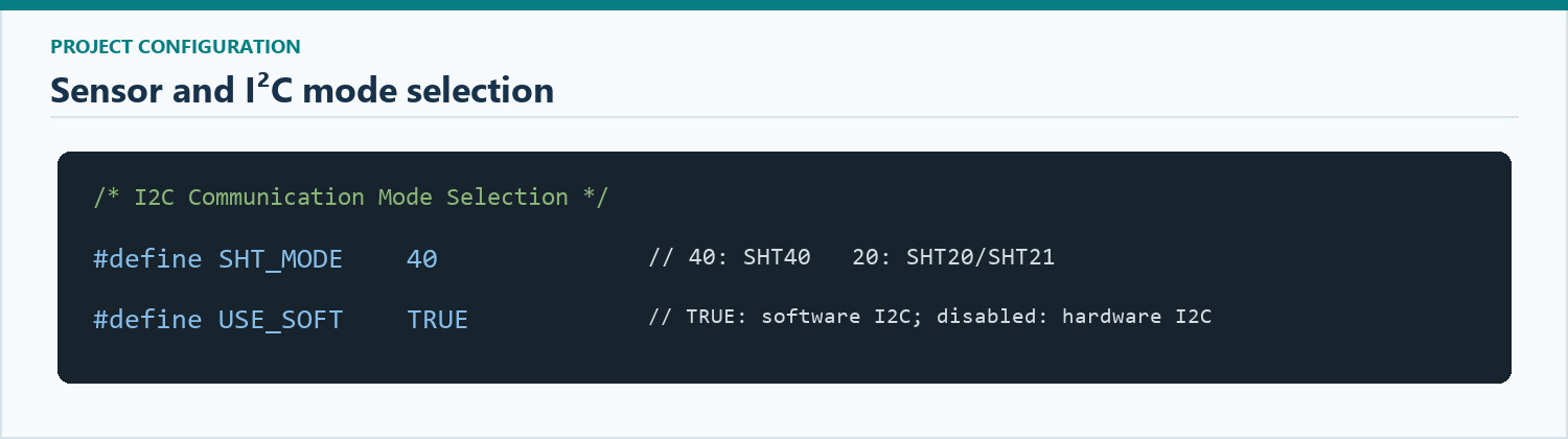
#define SHT_MODE 40
/* Leave USE_SOFT undefined for the source hardware-I2C path. */
/* #define USE_SOFT TRUE */
GPIOB_ModeCfg(GPIO_Pin_12 | GPIO_Pin_13, GPIO_ModeIN_PU);
I2C_Init(I2C_Mode_I2C, 100000, I2C_DutyCycle_16_9,
         I2C_Ack_Enable, I2C_AckAddr_7bit, 0);

/* The source passes this shifted form to I2C_Send7bitAddress(). */
#define SHT40_ADDR_FOR_SOURCE_API (0x44u << 1)
External resistors remain necessary when the MCU's internal pull-ups are too weak for the chosen bus capacitance and speed. Multiple breakout boards may already contain pull-ups; their parallel combination changes the effective resistance.
2. Read one SHT40 measurement in the correct order
The SHT40 high-repeatability command is one byte, 0xFD. Its response is exactly six bytes: temperature MSB, temperature LSB, temperature CRC, humidity MSB, humidity LSB, humidity CRC. The current Sensirion SHT4x datasheet gives a maximum high-repeatability measurement duration of 8.3 ms; its quick-start example waits 10 ms. Those are sensor timing figures, not a timeout for a stalled CH58x peripheral.
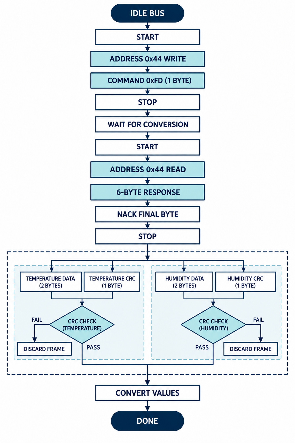
- Write: START, address
0x44with write direction, send0xFD, then STOP. - Wait: allow the sensor to finish conversion. If read-address polling is used instead of a fixed delay, a busy SHT40 can NACK the read header.
- Read: START, address
0x44with read direction, receive six bytes, NACK the final byte, then STOP. - Validate: independently check each two-byte data word against its following CRC byte. Reject the complete frame if either check fails.
- Convert: apply the SHT4x equations only to a valid frame. Clamp RH to 0–100% only if the application requires a display-range value; retain raw data for diagnostics.
An I²C ACK confirms that something answered at the address; it does not prove a valid SHT40 measurement. A plausible temperature also cannot substitute for CRC validation. The sensor does not stretch the clock during its measurement, and its measurement data is consumed after the first acknowledged read header. If a read fails, issue a new measurement command rather than assuming the old sample is still available. Sensirion SHT4x datasheet, §§4.1–4.6.
3. Put the protocol into CH58x firmware
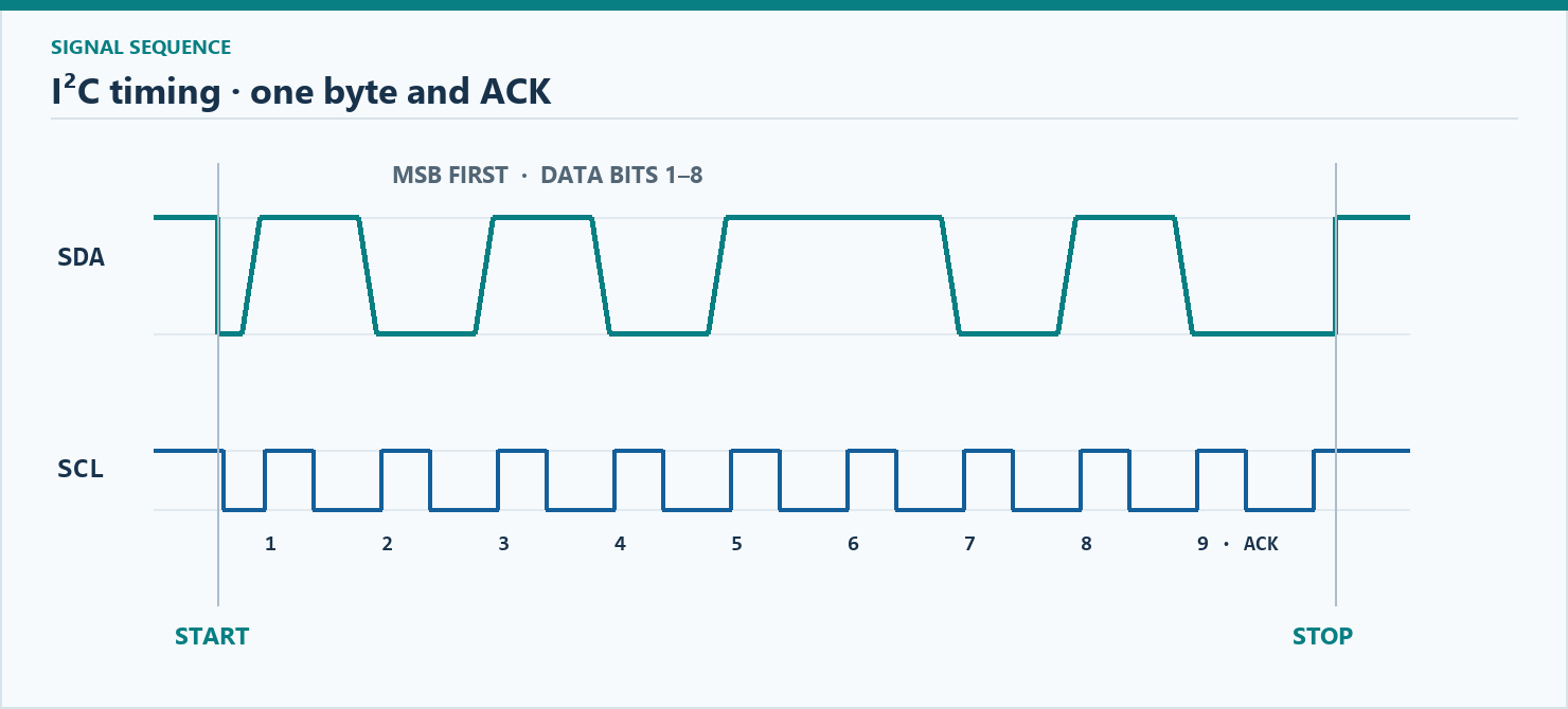
The code below keeps the SHT40 command, response order, CRC and conversion separate from the installed CH58x EVT. It is a portable protocol core, not a complete CH585 firmware project. Connect its three bus callbacks to the hardware-I²C or software-I²C implementation actually used by your project. The write callback must emit STOP; the read callback must NACK the sixth byte and emit STOP. Both must return on NACK or timeout rather than waiting indefinitely for an event flag.
#include <stdbool.h>
#include <stddef.h>
#include <stdint.h>

/* Each adapter call must finish its own I2C transaction with STOP.
   read() must fill all six bytes, NACK byte 6 before STOP,
   and both calls need a timeout. */
typedef struct {
    bool (*write)(uint8_t address7, const uint8_t *data,
                  size_t length, uint32_t timeout_ms);
    bool (*read)(uint8_t address7, uint8_t *data,
                 size_t length, uint32_t timeout_ms);
    void (*delay_ms)(uint32_t time_ms);
} sht40_bus_t;

typedef struct { float temperature_c; float humidity_rh; } sht40_data_t;
typedef enum { SHT40_OK, SHT40_ARGUMENT, SHT40_WRITE,
               SHT40_READ, SHT40_CRC } sht40_result_t;

static uint8_t sht4x_crc8(const uint8_t data[2])
{
    uint8_t crc = 0xFF;
    for (unsigned i = 0; i < 2; ++i) {
        crc ^= data[i];
        for (unsigned bit = 0; bit < 8; ++bit)
            crc = (crc & 0x80) ? (uint8_t)((crc << 1) ^ 0x31)
                               : (uint8_t)(crc << 1);
    }
    return crc;
}

sht40_result_t sht40_measure(const sht40_bus_t *bus, sht40_data_t *out)
{
    if (!bus || !out || !bus->write || !bus->read || !bus->delay_ms)
        return SHT40_ARGUMENT;

    const uint8_t command = 0xFD;       /* high repeatability */
    uint8_t rx[6];                      /* T MSB, T LSB, T CRC,
                                         RH MSB, RH LSB, RH CRC */
    if (!bus->write(0x44, &command, 1, 20)) return SHT40_WRITE;
    bus->delay_ms(10);                  /* 8.3 ms max in datasheet */
    if (!bus->read(0x44, rx, 6, 20))     return SHT40_READ;

    if (sht4x_crc8(&rx[0]) != rx[2] ||
        sht4x_crc8(&rx[3]) != rx[5])     return SHT40_CRC;

    uint16_t t = ((uint16_t)rx[0] << 8) | rx[1];
    uint16_t h = ((uint16_t)rx[3] << 8) | rx[4];
    out->temperature_c = -45.0f + 175.0f * t / 65535.0f;
    out->humidity_rh = -6.0f + 125.0f * h / 65535.0f;
    return SHT40_OK;
}

/* Datasheet CRC test vector: sht4x_crc8({0xBE, 0xEF}) == 0x92. */
Use CRC8(0xBE, 0xEF) = 0x92 as a unit check for the CRC routine. The SHT40 conversion equations are T = −45 + 175 × rawT / 65535 °C and RH = −6 + 125 × rawRH / 65535 %RH. Both CRC bytes must pass before either reported value is accepted. Sensirion SHT4x datasheet, Tables 7–8.
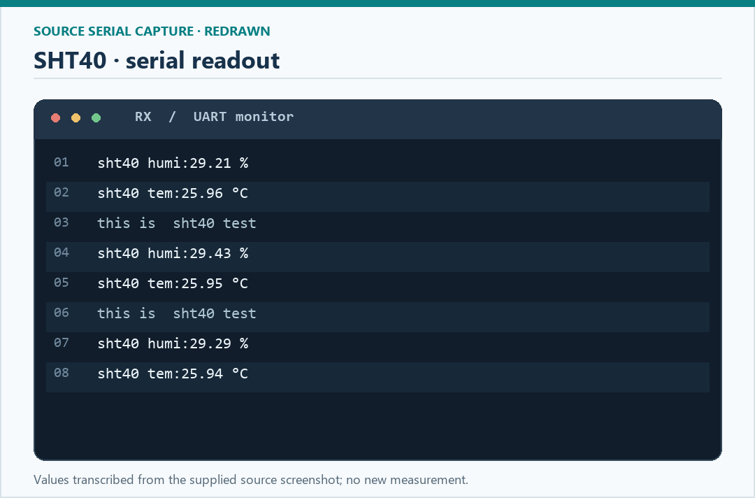
In the supplied source's UART printout, the temperature and humidity lines demonstrate the output format. During your own bring-up, log the six raw bytes and the specific failure stage (write NACK, read NACK/timeout, temperature CRC or humidity CRC); that record is more diagnostic than logging converted values alone.
4. Keep the SHT20 path separate
An SHT20 can use the same two-wire physical bus, but it is not an SHT40 command-compatible device. The SHT20 uses 7-bit address 0x40 and separate temperature/humidity commands. Its hold-master mode can hold SCL low while measuring; the SHT40 instead NACKs a premature read header. At the SHT20 default resolution, the datasheet lists maximum durations of 85 ms for temperature and 29 ms for RH, so reusing the SHT40's 10 ms wait would be wrong. Sensirion SHT20 datasheet, §§5.3–5.4.
| Decision | SHT40 | SHT20 |
|---|---|---|
| 7-bit address | 0x44 for this part | 0x40 |
| Measurement command | 0xFD returns T and RH together | 0xE3 T / 0xE5 RH in hold-master mode |
| Response | Six bytes: T+CRC, RH+CRC | Two data bytes and optional checksum for each measurement |
| Waiting behavior | Read header NACK while busy; no clock stretching | Hold-master mode may hold SCL low during conversion |
| Conversion | Divide raw values by 65535 | Clear the two status bits; divide by 65536 |
/* SHT20 conversion only; CRC and I2C handling remain separate. */
uint16_t rh_ticks = (uint16_t)(raw_rh_word & 0xFFFCu);
uint16_t t_ticks  = (uint16_t)(raw_t_word  & 0xFFFCu);
float humidity_rh = -6.0f + 125.0f * rh_ticks / 65536.0f;
float temperature_c = -46.85f + 175.72f * t_ticks / 65536.0f;
Use a separate result for each SHT20 command, as shown above. If the controller cannot support hold-master clock stretching, review the datasheet's no-hold mode timing rather than only changing the command byte. The SHT20 user register must be read before changing the heater bit so reserved bits are preserved; leave the heater off for ordinary ambient comparisons. Sensirion SHT20 datasheet, §§5.6 and 6.
5. Hardware I²C or software I²C?
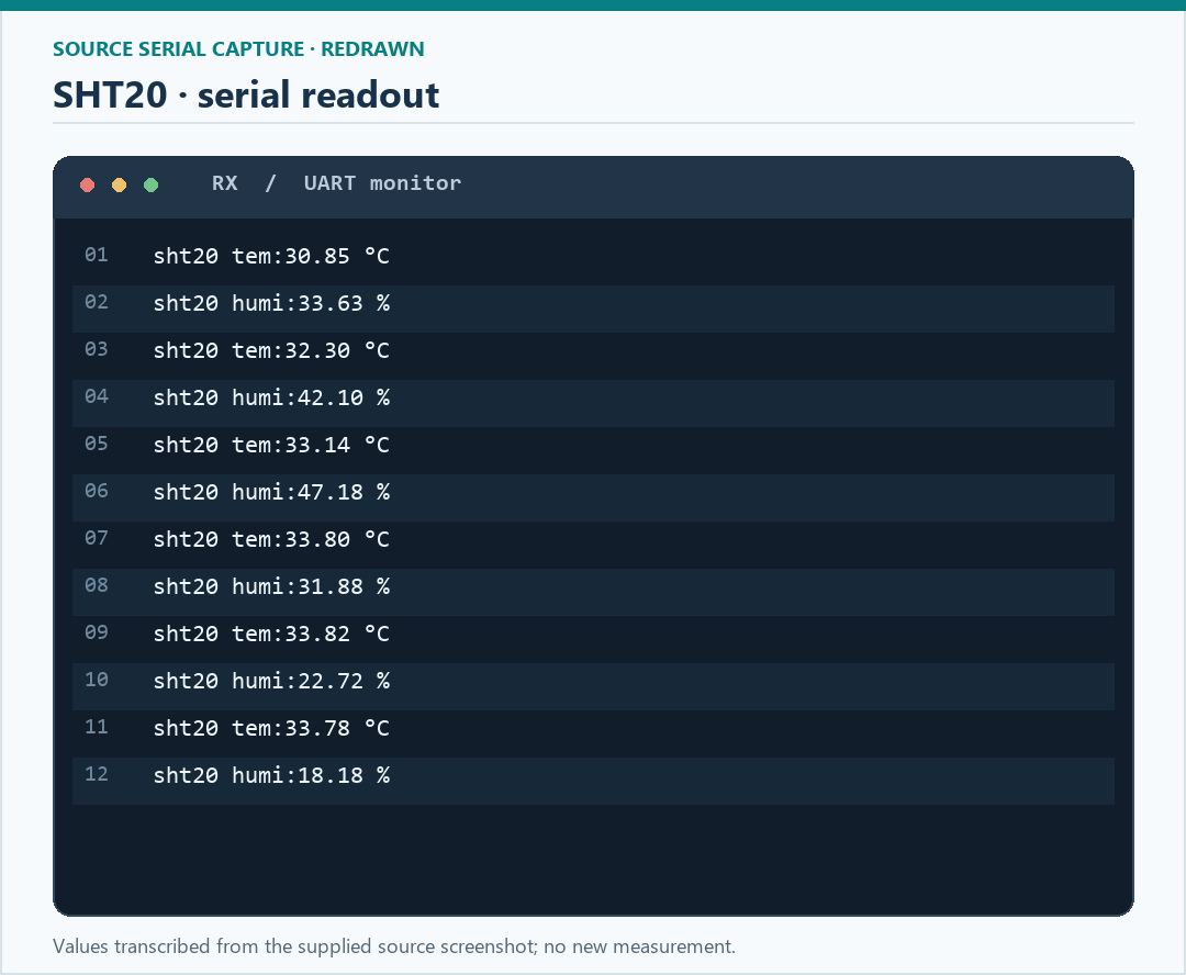
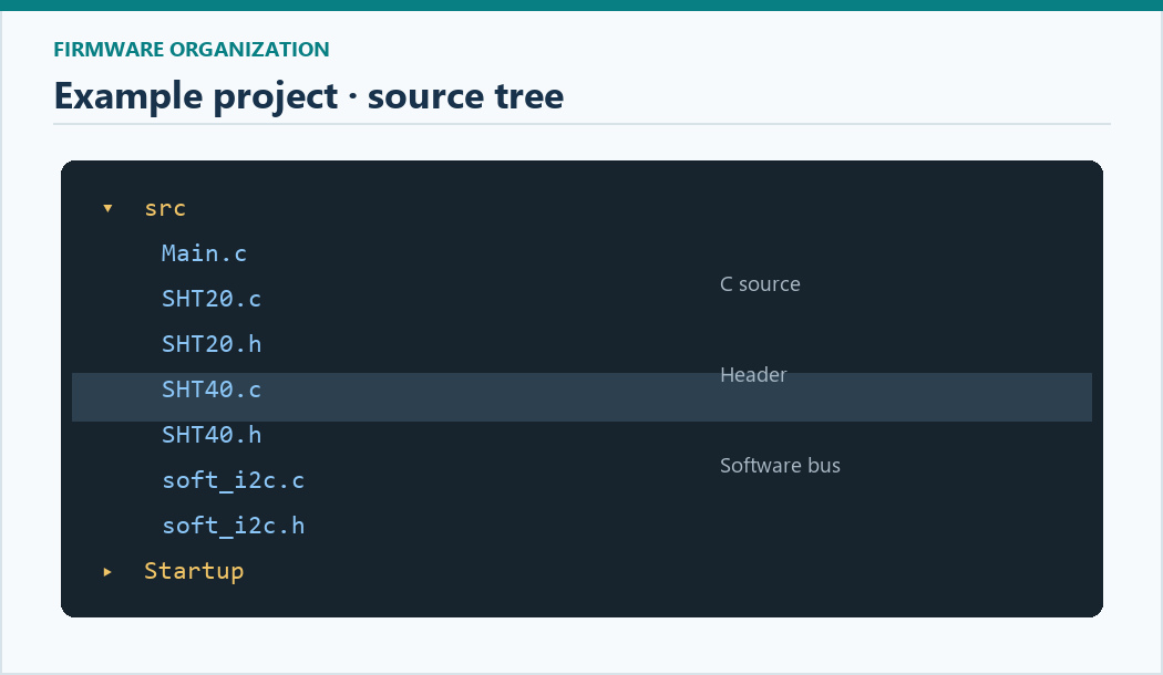
The supplied project tree contains separate SHT20, SHT40 and bit-banged I²C files. Choose one bus implementation before tracing a failure: hardware-I²C event flags and GPIO software timing fail in different ways. In the supplied example, defining USE_SOFT selects the software path, while commenting out that definition selects hardware I²C. Setting the macro to FALSE may still select software if the source uses #ifdef USE_SOFT; inspect the installed project's conditional compilation before building.
For software I²C, release SDA and SCL as open-drain signals, sample SDA while SCL is high, and NACK the final SHT40 response byte. The receive excerpt below expresses the source project's byte-level logic; its GPIO helpers must supply the line release and timing behavior. Verify that the chosen pins are available on the actual CH58x package and board.
/* Source-style bit-banged read; the surrounding GPIO helpers must
   release SDA for input and enforce timing at the chosen bus speed. */
uint8_t IIC_ReadByte(uint8_t ack)
{
    uint8_t value = 0;
    IIC_SDA_H();                         /* release open-drain SDA */
    for (unsigned bit = 0; bit < 8; ++bit) {
        IIC_SCL_L(); IIC_Delay();
        IIC_SCL_H(); IIC_Delay();
        value = (uint8_t)((value << 1) | (SDA_read() ? 1u : 0u));
    }
    IIC_SCL_L();
    if (ack) IIC_SDA_L(); else IIC_SDA_H();
    IIC_Delay(); IIC_SCL_H(); IIC_Delay(); IIC_SCL_L();
    IIC_SDA_H();                         /* release SDA after ACK/NACK */
    return value;
}
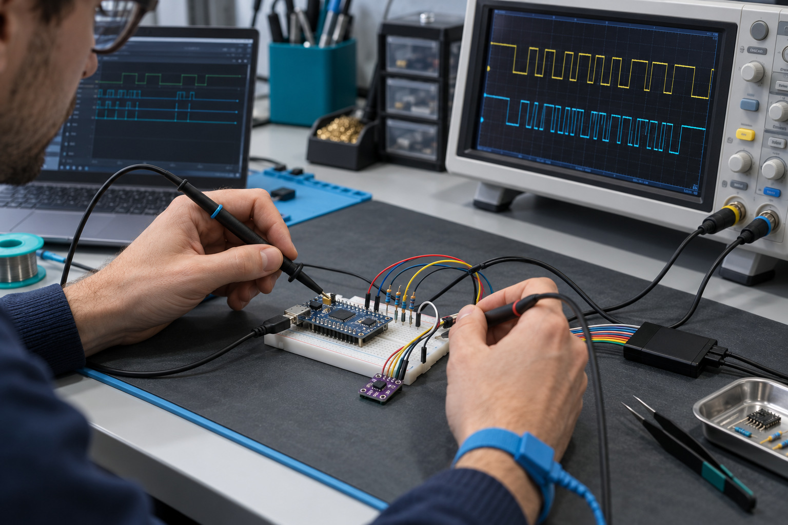
Neither a software delay loop nor a hardware flag wait should be unbounded. Set a timeout around START, address ACK, transfer complete and RXNE events. If SDA stays low before START, look for a held bus or wiring fault; do not repeatedly issue START without diagnosing the line.
6. Verify the result and choose the next check
| Observation | Likely boundary | Next check |
|---|---|---|
| SDA or SCL is low at idle | Electrical bus problem | Measure both lines at the sensor; check shorts, pull-ups and supply. |
| No ACK at address | Power, pin map or address representation | Check VDD/GND, PB12/PB13 or remap, and whether the SDK expects 0x44 or 0x88. |
| Write ACK, read NACK immediately | Conversion may still be running | Check write STOP, elapsed time and high-repeatability command byte 0xFD. |
| Six bytes arrive; CRC fails | Byte order, sampling or signal integrity | Log all six bytes; run the 0xBEEF → 0x92 CRC test and inspect waveforms. |
| CRC passes; converted RH is implausible | Formula, sensor identification or placement | Confirm the model, apply the matching equation and compare the sensor's air path with a reference. |
Before release, run repeated reads on the selected CH58x board at the intended supply, bus speed and cable length; record NACK, timeout and CRC counts as well as converted values. Keep the MCU adapter's event sequence and ACK/NACK handling matched to the installed EVT release; the SHT40 core above does not define those library internals.
CH58x–SHT40 I²C FAQ
Should I use 0x44 or 0x88 for an SHT40 on a CH585?
The SHT40 device address is 0x44 in 7-bit notation. The cited CH58x source passes 0x88 to an API that expects the address shifted left by one bit. Check the installed EVT function's address convention before changing firmware.
Why does the SHT40 ACK the write but NACK the read?
The sensor can NACK a read header while a measurement is still running. After sending the one-byte 0xFD command, end the write with STOP and allow conversion time; Sensirion's quick-start example waits 10 ms for this high-repeatability command. Also check power, wiring and the address format if the NACK persists.
What must be checked in the six-byte SHT40 response?
The frame contains two temperature bytes and their CRC, followed by two humidity bytes and their CRC. Validate both CRC-8 bytes before converting or accepting either measurement. The CRC polynomial is 0x31 with initialization value 0xFF.
Can the same SHT40 driver read an SHT20?
No. The SHT20 uses 7-bit address 0x40, different temperature and humidity commands, different waiting behavior and different conversion equations. The physical I²C bus may be shared, but the device protocol and validation path must remain separate.
Technical references
Sensirion SHT4x datasheet · Sensirion SHT20 datasheet · CH58x I²C source example