SHT30 Reads High Near an ESP32: Why Calibration Offset Is Not the First Fix | FHT30
An SHT30 can return valid I²C frames and still report a temperature two or three degrees above the air you intended to measure. Before changing calibration, determine whether the sensor is measuring the room, a warm PCB, or air already heated inside the enclosure.
Direct answer
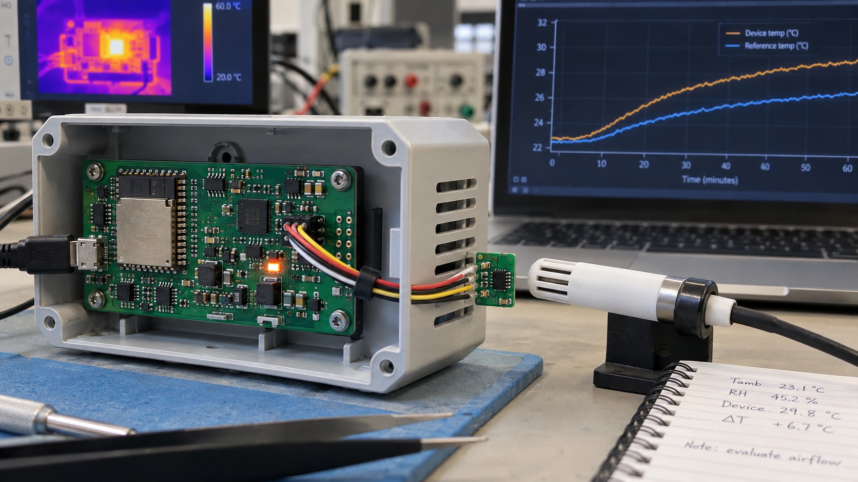
A high SHT30 reading beside an ESP32 is not automatically a calibration error. If the error grows after boot, changes with Wi-Fi activity, increases when the enclosure is closed, or falls when the sensor is moved away from the main PCB, the dominant cause is probably thermal coupling.
A fixed offset can hide one operating point while making other states worse. The first fix is to identify the heat path and reduce it. Calibration belongs at the end, after the remaining error is stable, repeatable and measured against a suitable reference.
FAST SCREENING TEST
A 30-minute check before changing calibration
This short test does not qualify the design. It tells you whether the reported offset is strongly coupled to operating state and therefore unlikely to be solved by one fixed correction.
- Stabilize firstWith the enclosure open, place a characterized reference probe in the air at the product inlet. Do not let it touch the PCB or housing.
- Log the idle stateRun normal sensor acquisition for five minutes with Wi-Fi, display backlight, charging and other optional loads inactive.
- Apply the deployed loadRun the real radio and display duty cycle for five minutes without changing the sensor command or sample interval.
- Close the enclosureContinue logging for at least ten minutes. Treat the result as a trend if the assembly has not reached thermal equilibrium.
- Compare the changeCalculate
ΔT = Tsensor - Treferencefor each phase. A changing ΔT identifies a state-dependent thermal problem.
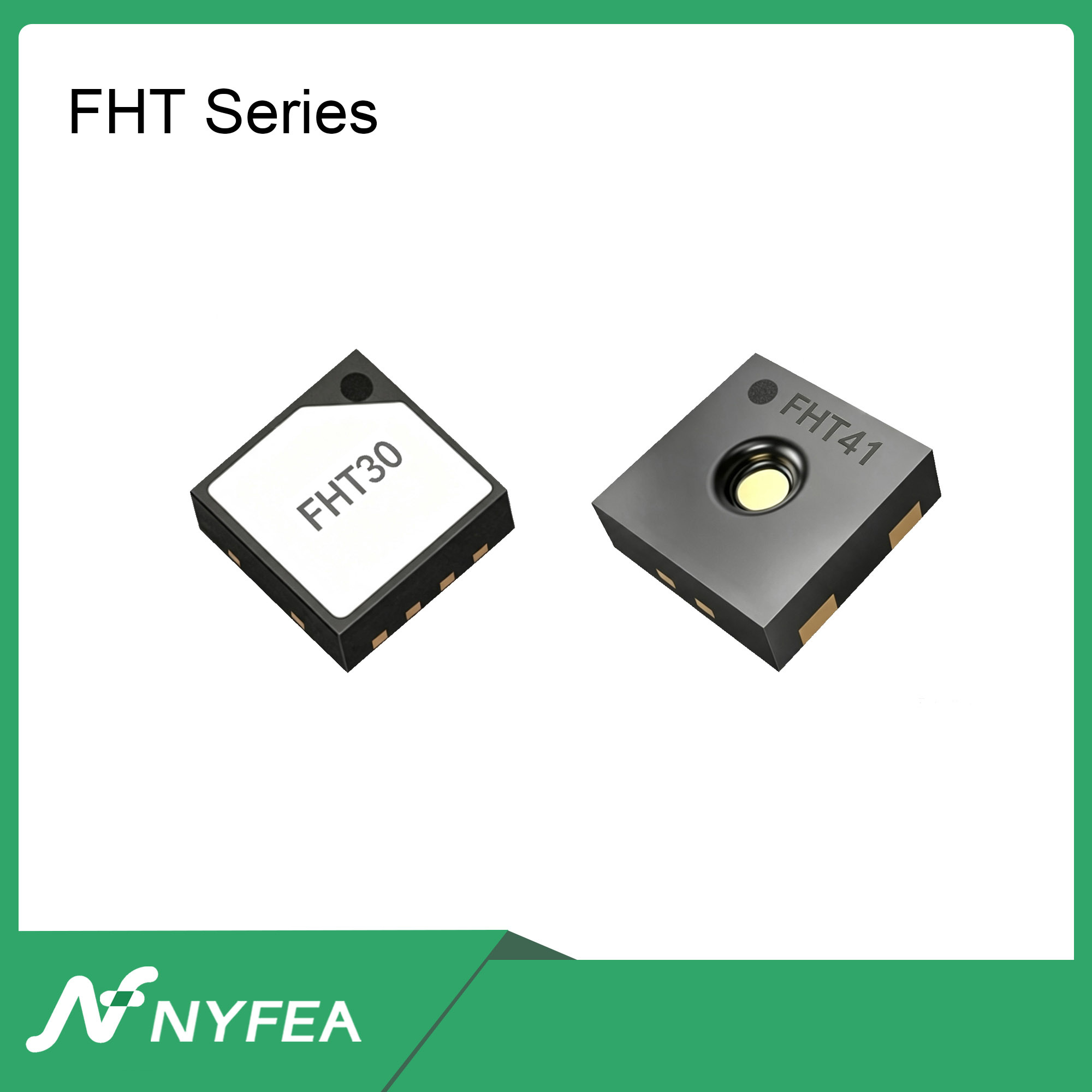
Teams considering FHT30 should preserve this SHT30 trace as the reference baseline. The complete A/B method appears after the thermal diagnosis.
Sensor accuracy and system accuracy are different questions
A humidity sensor reports the conditions at its sensing element, not the conditions at an abstract point called “room temperature.” A datasheet accuracy limit describes the device under specified test conditions. Once the device is soldered beside a processor, regulator, display connector or battery charger, the complete assembly creates a measurement system with its own temperature gradients and airflow.
Consider a hypothetical case: a suitable external reference reads 23.5 °C while the SHT30 reports 26 °C, with clean communication and repeatable data. The sensor may be reporting its local temperature correctly. The unresolved question is whether that local temperature represents the air the product claims to measure.
Do not start with “How many degrees should I subtract?”
Start with “Which thermal node is the sensor following?” If the answer changes with processor load or enclosure state, the error is state-dependent and cannot be represented by one universal constant.
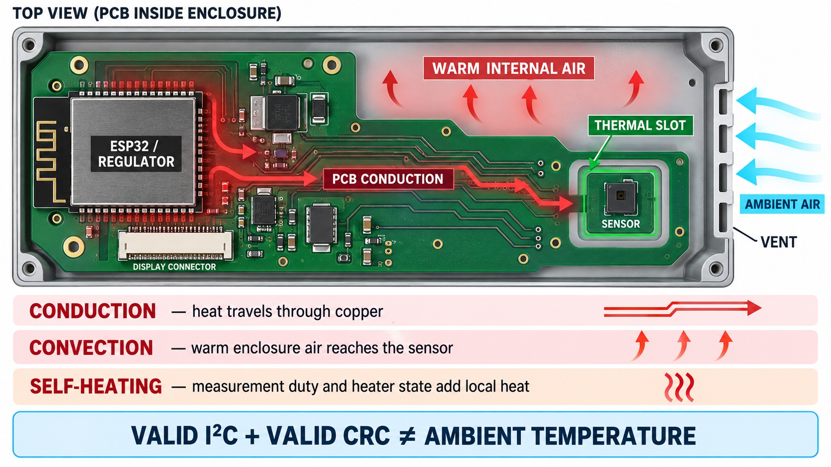
Three heat paths can produce an electrically valid but thermally biased reading
Conduction through the PCB
Copper planes and traces carry heat from an ESP32, regulator, radio power stage or display circuit toward the sensor pads. Short distance, wide copper and uninterrupted ground pours make that path stronger.
Warm air inside the enclosure
The sensor may be physically separated from the processor but still sit in a pocket of air warmed by the electronics. Small vents, dead volume and a poor air path increase the delay and steady-state rise.
Local self-heating
The sensing IC dissipates some power during measurements. Excessive acquisition rate or an enabled heater adds local heat. In many ESP32 products this is smaller than board and enclosure heating, but it must still be controlled.
Relative humidity provides an important clue. When the air near the sensor is warmed without adding water vapor, the reported relative humidity tends to fall. A temperature rise and RH drop that begin together after processor load increases are therefore consistent with local heating. They are not proof by themselves, but they are a useful reason to test the thermal design before editing calibration.
Why a fixed temperature offset often passes the bench and fails in use
Suppose a prototype reads 2.0 °C high on an open bench, so firmware subtracts 2.0 °C. That correction is valid only if the thermal error remains 2.0 °C across every relevant state. In practice, an ESP32 product may move between radio sleep, Wi-Fi transmit bursts, display activity, charging, fan operation and deep sleep. Each state changes heat generation and often changes airflow.
If the same assembly shows +1.0 °C in free air and +3.0 °C after enclosure closure, a -2.0 °C correction over-corrects one state and under-corrects the other. The table below uses the movement of the error, rather than one absolute reading, to select the next test.
| Observed pattern | Likely interpretation | Next discriminating test |
|---|---|---|
| Error grows for several minutes after boot | Assembly warm-up, not a static calibration constant | Log the reference, sensor and processor state from cold start |
| Temperature rises during Wi-Fi or display activity | Load-dependent PCB conduction or internal-air heating | Repeat with radio/display disabled while keeping acquisition unchanged |
| Temperature rises and RH falls together | Local air is being heated near the sensor | Add a remote reference probe at the sensor inlet |
| Bias increases after the cover is installed | Ventilation, dead volume or heat recirculation dominates | Compare cover open, cover closed and forced-air exchange |
| Bias collapses on a remote daughterboard | Main-board thermal coupling is the primary path | Add distance, narrow traces or a thermal slot to the target design |
| Nearly constant residual remains in all stable states | Calibration or reference uncertainty may now be relevant | Verify at multiple temperature/RH points with a suitable reference |
A five-state test that separates thermal coupling from calibration
Use one time-aligned log for the device under test, an independently positioned reference, processor state, enclosure state and major power loads. Keep the sensor command, measurement repeatability and sample interval constant while changing one system variable at a time.
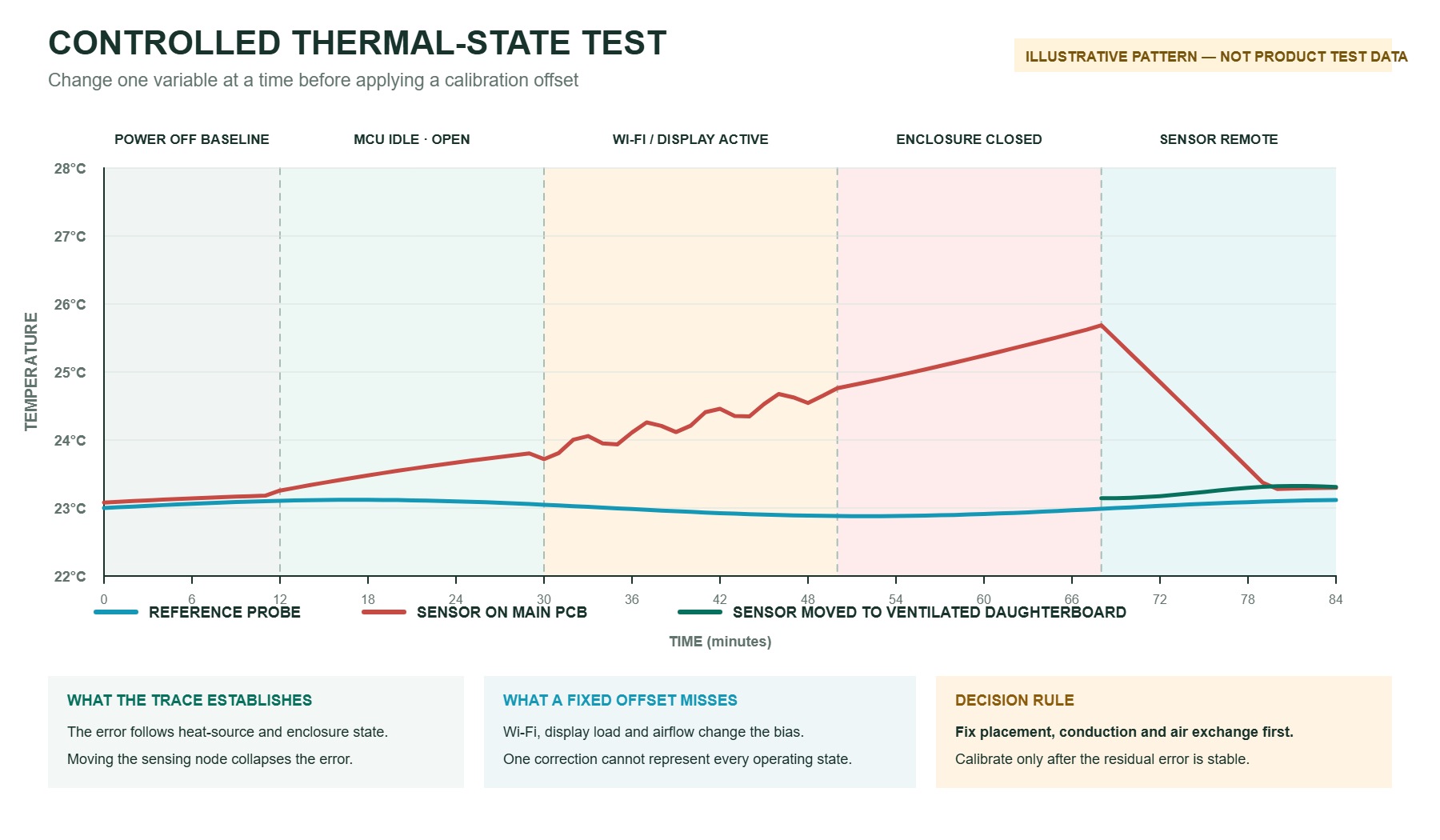
- Establish the ambient baseline.Place the unpowered assembly and reference in the same stable environment long enough for temperatures to equalize. Record reference stability and the intended measurement location.
- Power the MCU at minimum load with the enclosure open.Start normal sensor acquisition, but hold Wi-Fi, display backlight, charging and other major loads inactive. Record the warm-up curve, not just the final value.
- Apply the real electrical load.Enable the radio, display and duty cycles used in the product. A repeatable slope change tied to load is stronger evidence than a single spot comparison.
- Close the production enclosure.Use the intended vents, seals, cable openings and orientation. Continue until both the board and the reference reach a meaningful steady condition.
- Move only the sensing location.Repeat with the sensor on a small ventilated daughterboard or flex, away from hot copper. If the error shrinks while firmware and reference remain unchanged, placement is the discriminating variable.
Calculate evidence, not just an average offset
For each stable phase, calculate ΔT = Tsensor - Treference. Then compare how that error changes between states. Product-specific pass limits should come from the system error budget; the metrics below define what must be measured without inventing universal thresholds.
- Load-induced shift
ΔTload - ΔTidleshows whether ESP32 and peripheral activity changes the error.- Enclosure penalty
ΔTclosed - ΔTopenisolates the effect of restricted air exchange and internal heat accumulation.- Placement benefit
ΔTcoupled - ΔTremotemeasures the improvement attributable to sensor isolation.- Warm-up behavior
- Record the time and slope until the reading remains inside the project-defined stability band.
- Humidity correlation
- Compare RH error with temperature rise. A repeatable RH decrease during local warming supports a thermal explanation.
Measure the same air, not merely nearby air
- Use a characterized reference whose uncertainty is small enough for the product error budget. A second unverified hobby sensor is a comparison device, not an absolute standard.
- Place the reference and DUT in the same air path without allowing either probe to touch the PCB, enclosure wall or each other.
- Keep hands, direct sunlight, lamps and temporary fan drafts away from the test volume; each can create a local temperature gradient.
- Allow for different response times. Compare stabilized values and time-aligned transitions instead of choosing the moment when two displays happen to agree.
- Document reference position, orientation, enclosure condition and ambient stability so another engineer can repeat the test.
Log enough context to explain the trace
For each sample, store elapsed time, raw temperature and RH, reference values, processor mode, radio activity, display state, supply current if available, enclosure state and heater state. A CSV with these fields is more useful than a photograph of two displays because it preserves timing and exposes correlation.
Rule out the heater and acquisition pattern before blaming calibration
The SHT3x heater is intended for situations such as condensation recovery; it is not a general accuracy enhancer. When active, it intentionally warms the sensing element, so temperature rises and relative humidity falls. ESPHome documents the heater as disabled by default, but a reused driver, startup sequence or application command can change that state. Confirm it from the actual firmware path rather than assuming the configuration.
Polling also matters. Compare the deployed acquisition interval with a slower controlled interval while keeping the processor load unchanged. If the sensor reading changes only with sample rate, local dissipation is implicated. If it follows Wi-Fi, a regulator or enclosure closure instead, the larger system heat path is more likely.
Core diagnostic code: log the thermal evidence
This Arduino-ESP32 example deliberately avoids a convenience sensor library so the command, conversion delay, two CRC checks and heater-status bit remain visible. It issues one high-repeatability, no-clock-stretching measurement per second and writes a CSV record suitable for a time-aligned thermal trace.
#include <Arduino.h>
#include <Wire.h>

constexpr uint8_t  SHT30_ADDRESS    = 0x44;
constexpr uint16_t CMD_MEASURE_HIGH = 0x2400; // single shot, no clock stretching
constexpr uint16_t CMD_READ_STATUS  = 0xF32D;
constexpr uint16_t CMD_HEATER_OFF   = 0x3066;
constexpr uint32_t SAMPLE_PERIOD_MS = 1000;

enum class ReadResult : uint8_t { Ok, I2cError, CrcError };

struct Reading {
  uint16_t rawTemperature;
  uint16_t rawHumidity;
  float temperatureC;
  float humidityPct;
};

const char* testPhase = "idle_open";
uint32_t crcErrors = 0;
uint32_t i2cErrors = 0;

uint8_t crc8(const uint8_t data[2]) {
  uint8_t crc = 0xFF;
  for (uint8_t i = 0; i < 2; ++i) {
    crc ^= data[i];
    for (uint8_t bit = 0; bit < 8; ++bit) {
      crc = (crc & 0x80) ? uint8_t((crc << 1) ^ 0x31)
                         : uint8_t(crc << 1);
    }
  }
  return crc;
}

bool sendCommand(uint16_t command) {
  Wire.beginTransmission(SHT30_ADDRESS);
  Wire.write(uint8_t(command >> 8));
  Wire.write(uint8_t(command));
  return Wire.endTransmission() == 0;
}

ReadResult readMeasurement(Reading& value) {
  if (!sendCommand(CMD_MEASURE_HIGH)) return ReadResult::I2cError;
  delay(20); // exceeds the maximum high-repeatability conversion time

  if (Wire.requestFrom(SHT30_ADDRESS, uint8_t(6)) != 6) {
    while (Wire.available()) Wire.read();
    return ReadResult::I2cError;
  }

  uint8_t frame[6];
  for (uint8_t i = 0; i < 6; ++i) frame[i] = Wire.read();

  if (crc8(&frame[0]) != frame[2] || crc8(&frame[3]) != frame[5]) {
    return ReadResult::CrcError;
  }

  value.rawTemperature = (uint16_t(frame[0]) << 8) | frame[1];
  value.rawHumidity    = (uint16_t(frame[3]) << 8) | frame[4];
  value.temperatureC  = -45.0f + 175.0f * value.rawTemperature / 65535.0f;
  value.humidityPct   = 100.0f * value.rawHumidity / 65535.0f;
  return ReadResult::Ok;
}

ReadResult readStatus(uint16_t& status) {
  if (!sendCommand(CMD_READ_STATUS)) return ReadResult::I2cError;
  delay(1);
  if (Wire.requestFrom(SHT30_ADDRESS, uint8_t(3)) != 3) {
    while (Wire.available()) Wire.read();
    return ReadResult::I2cError;
  }

  uint8_t frame[3];
  for (uint8_t i = 0; i < 3; ++i) frame[i] = Wire.read();
  if (crc8(frame) != frame[2]) return ReadResult::CrcError;

  status = (uint16_t(frame[0]) << 8) | frame[1];
  return ReadResult::Ok;
}

void countError(ReadResult result) {
  if (result == ReadResult::CrcError) ++crcErrors;
  if (result == ReadResult::I2cError) ++i2cErrors;
}

void updateTestPhase() {
  if (!Serial.available()) return;
  switch (Serial.read()) {
    case '1': testPhase = "idle_open";     break;
    case '2': testPhase = "load_open";     break;
    case '3': testPhase = "load_closed";   break;
    case '4': testPhase = "sensor_remote"; break;
    default: break;
  }
}

void setup() {
  Serial.begin(115200);
  Wire.begin(SDA, SCL, 100000);
  if (!sendCommand(CMD_HEATER_OFF)) ++i2cErrors;
  delay(2);
  Serial.println("ms,phase,raw_t,raw_rh,temp_c,rh_pct,status,status_ok,heater,crc_errors,i2c_errors");
}

void loop() {
  updateTestPhase();
  static uint32_t nextSample = 0;
  const uint32_t now = millis();
  if (int32_t(now - nextSample) < 0) return;
  nextSample = now + SAMPLE_PERIOD_MS;

  Reading reading{};
  uint16_t status = 0;
  const ReadResult measurementResult = readMeasurement(reading);
  const ReadResult statusResult = readStatus(status);
  countError(measurementResult);
  countError(statusResult);

  const bool statusOk = statusResult == ReadResult::Ok;
  const unsigned heaterOn = statusOk && (status & (1u << 13)) ? 1u : 0u;

  if (measurementResult != ReadResult::Ok) {
    Serial.printf("%lu,%s,,,,,0x%04X,%u,%u,%lu,%lu\n",
                  now, testPhase, status, statusOk, heaterOn, crcErrors, i2cErrors);
    return;
  }

  Serial.printf("%lu,%s,0x%04X,0x%04X,%.3f,%.3f,0x%04X,%u,%u,%lu,%lu\n",
                now, testPhase, reading.rawTemperature, reading.rawHumidity,
                reading.temperatureC, reading.humidityPct, status, statusOk,
                heaterOn, crcErrors, i2cErrors);
}- Send
1,2,3or4through the serial monitor when the test enters idle/open, load/open, load/closed or remote-sensor state. - Keep the firmware, measurement command and one-second interval unchanged while changing only the intended thermal variable.
- Use the SHT30 trace as the baseline. For an FHT30 A/B test, retain the same CSV fields and state sequence, but confirm the exact FHT30 command set, timing and conversion formula before reusing this low-level driver.
Fix the heat path before compensating the number
The most effective change depends on which path the state test identifies. The objective is not simply to make the sensor colder. It is to make the sensing element track the intended external air with a predictable time constant.
PCB placement
- Increase distance from the ESP32, regulator, charger, display connector and high-current copper.
- Place the sensor near the air inlet rather than in the board's thermal center.
- Avoid routing heat-spreading planes directly beneath the sensing area.
Thermal isolation
- Use narrow copper connections where electrical and EMC constraints allow.
- Add milled slots around a sensor tongue to reduce conducted heat.
- For demanding designs, use a small daughterboard or flex connection.
Air exchange
- Provide a short, open path between the sensing element and external air.
- Avoid a sealed pocket in which warm air from the processor accumulates.
- Check product orientation because natural convection changes with mounting.
Radiation and materials
- Keep the sensor away from warm displays, lamps and surfaces with direct radiant coupling.
- Prevent coatings, adhesives or membranes from unintentionally blocking the opening.
- Re-test after full assembly because housings and filters change response time.
After a layout or enclosure change, repeat the same five-state sequence. Improvement should appear as a smaller load-correlated rise, faster tracking of the external reference and less difference between open and closed enclosure states. Without the repeated test, a design change is only a plausible story.
Would replacing SHT30 with FHT30 remove the offset?
Not automatically. FHT30 is relevant when a team is evaluating an SHT30-class digital temperature and humidity sensor, but a component change cannot eliminate heat generated elsewhere in the product. If FHT30 is mounted on the same warm copper and exposed to the same trapped air, it can inherit the same system-level bias even when its digital communication and individual accuracy are acceptable.
The useful comparison is therefore not “Which value looks closer on one bench?” It is an A/B experiment in which SHT30 and FHT30 experience the same board location, firmware state, acquisition interval, airflow and reference. Then repeat the comparison with both devices thermally isolated. That creates four results: SHT30 coupled, FHT30 coupled, SHT30 isolated and FHT30 isolated. The pattern separates device behavior from integration behavior.
How to read the four results
If both devices read high when coupled and both improve when isolated, the PCB or enclosure is the dominant cause. If one device retains a stable error after both are isolated, compare its measurement settings, reference uncertainty and device-level performance. If the difference appears only at a particular sample rate or heater state, resolve the firmware condition before comparing accuracy.
| Evidence to hold constant | Why it matters | Release observation |
|---|---|---|
| Reference and physical position | A few centimeters can place the probe in a different thermal node | Steady-state error and response time at the claimed measurement point |
| Firmware commands and sample interval | Different acquisition or heater behavior changes dissipation | Warm-up trace, heater state and repeatability |
| ESP32 and peripheral workload | Radio, display and charging loads change the heat source | Error versus each defined power state |
| Open and closed enclosure | Ventilation and internal air temperature are product properties | Enclosure-induced shift and recovery time |
| Coupled and isolated placement | This distinguishes device residual from integration bias | Reduction attributable to the thermal design change |
| Multiple samples and lots | One sample cannot establish production distribution | Mean, spread, outliers and post-process stability |
Only after thermal coupling has been reduced should a team compare any stable residual error with the product error budget. That is the point at which device accuracy, reference uncertainty, production spread and a justified calibration method can be discussed without mixing them with board heating.
A release checklist built around thermal evidence
Use this sequence to convert an SHT30 “reads high” complaint into evidence that can also qualify an FHT30 candidate.
- Freeze the referenceRecord the exact device, board revision, firmware, enclosure, orientation, sample interval and acceptance limits.
- Verify the digital stateConfirm command path, heater state, measurement cadence, CRC handling and error recovery.
- Map operating statesLog cold start, MCU idle, Wi-Fi/display load, charging, sleep and any actuator state that changes dissipation.
- Separate the heat pathsCompare enclosure open/closed and sensor coupled/isolated while keeping software unchanged.
- Measure the residualAfter thermal stabilization, compare several temperature and RH points against a suitable reference.
- Prove production stabilityInclude multiple samples and lots, assembly processing, recovery, enclosure variation and defined pass/fail limits.
Engineering conclusion
When an SHT30 reads high near an ESP32, the decisive evidence is how ΔT changes with electrical load, enclosure state and sensor placement. Correct state-dependent thermal coupling first. Calibrate only the stable residual that remains after the heat path, heater state, acquisition method and reference setup are controlled. Apply the same sequence to FHT30 so that the comparison measures device behavior rather than the temperature of a warm board.
FAQ
Why does an SHT30 read 2 to 3 °C high near an ESP32?
Common causes are heat conducted through the PCB, warm air trapped inside the enclosure, direct thermal radiation, excessive acquisition activity or an enabled sensor heater. Correlate the error with processor load, enclosure state and sensor position before treating it as calibration error.
Can I simply subtract a fixed temperature offset?
Only after proving that the residual error is stable across the required temperature, humidity, power and enclosure states. An offset derived at one load can make other states less accurate when the dominant error is thermal coupling.
Why does relative humidity fall when the temperature reading rises?
If the local air is warmed without adding moisture, its relative humidity falls. A simultaneous temperature rise and RH drop can therefore indicate local heating, although a controlled reference test is still needed.
How can I distinguish sensor error from PCB heating?
Log a reference probe and the sensor from cold start, change one electrical load at a time, test the final enclosure, and then move only the sensor to a ventilated remote board. A large improvement after relocation identifies the integration path.
Should the SHT30 heater be enabled continuously?
No. The heater intentionally changes the local sensor temperature and is generally used for specific purposes such as condensation recovery. Confirm the exact device guidance and control it explicitly in firmware.
Can a slower measurement interval reduce self-heating?
It can reduce dissipation caused by acquisition, but it will not remove heat arriving from the ESP32, regulator or enclosure air. Change the interval as one controlled variable and compare the resulting trace.
Where should a temperature and humidity sensor sit inside an enclosure?
Place it close to the intended external-air inlet, away from major heat sources and uninterrupted copper planes, with enough open volume and ventilation for air exchange. Validate the actual mounting orientation and complete enclosure.
Would replacing SHT30 with FHT30 automatically remove the offset?
No. FHT30 should be evaluated under the same thermal conditions. If both devices occupy the same thermally coupled location, both can measure air or PCB conditions that differ from the intended ambient point.
When is calibration appropriate?
Calibration is appropriate after the heat path, heater state, acquisition method and reference setup are controlled and the remaining error is repeatable across the required operating range. Include reference uncertainty and production spread in the error budget.
Technical basis and disclosure
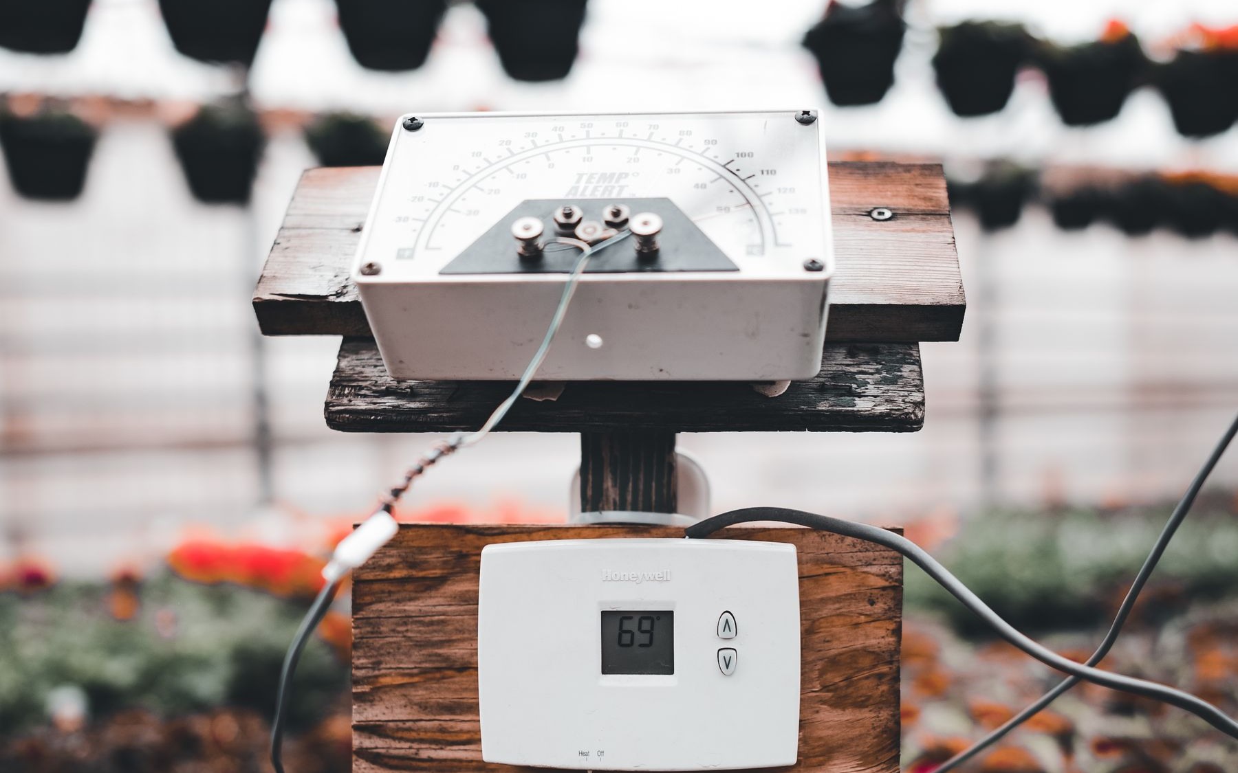
This article separates device behavior from system integration using primary technical guidance and a controlled-test method. Illustrations explain mechanisms and test logic; they are not NYFEA or Sensirion product test data. The greenhouse photograph documents a real application environment, not the identity or performance of the sensing IC inside that equipment.
- Sensirion SHT3x-DIS datasheet: device characteristics, heater behavior and application-dependent response.
- ESPHome SHT3xD documentation: heater configuration and practical integration context.
- NYFEA FHT30 technical information: candidate-device information for project-specific evaluation.
Disclosure: NYFEA supplies FHT30. No universal drop-in or accuracy claim is made here; suitability must be demonstrated in the target hardware, firmware, enclosure and production process.
Evaluate FHT30 against the thermal behavior of your SHT30 design
For a project-specific review, provide the board layout around the sensor, enclosure and vent geometry, firmware acquisition interval, heater state, ESP32 power modes, reference method, operating range and error limits.