Arduino I²C Engineering
SHT31, HTU21D and AM2320 on One Arduino I²C Bus: Power, Pull-Ups and Valid Readings
SHT31, HTU21D and AM2320 can share one Arduino I²C bus, but different addresses alone do not guarantee safe wiring or valid readings. This guide shows how to verify power and pull-ups, read each device correctly, reject failed samples and compare results fairly.SHT3x-DIS is the next generation of Sensirion’s temperature and humidity sensors. It builds on a new CMOSens® sensor chip that is at the heart of Sensirion’s new humidity and temperature platform. The SHT3x-DIS has increased intelligence, reliability and improved accuracy specifications compared to its predecessor.
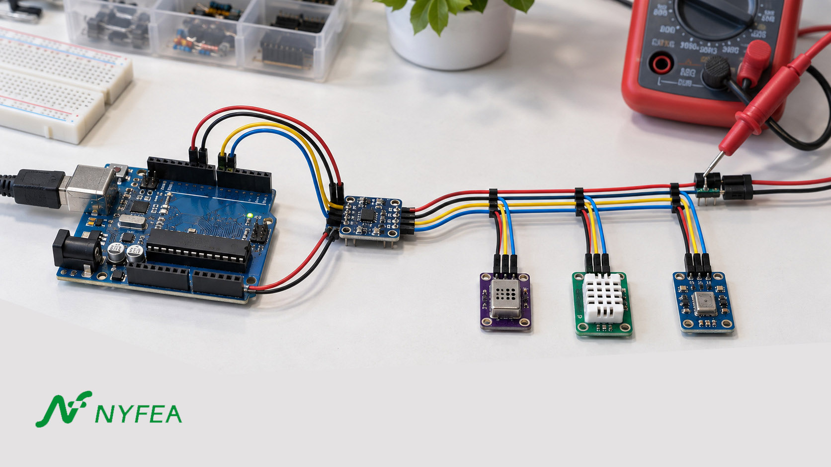
Can SHT31, HTU21D and AM2320 share one Arduino I²C bus?
Yes, if their installed boards are electrically compatible and the firmware handles each device separately. SHT31 uses 0x44 or 0x45, HTU21D uses 0x40, and AM2320 uses 0x5C as 7-bit addresses. A unique address avoids a bus collision; it does not approve 5 V wiring, validate pull-ups or prove that a returned humidity value is correct. Confirm the actual module schematic before wiring. Sensirion SHT3x datasheet
How three sensors share one I²C bus
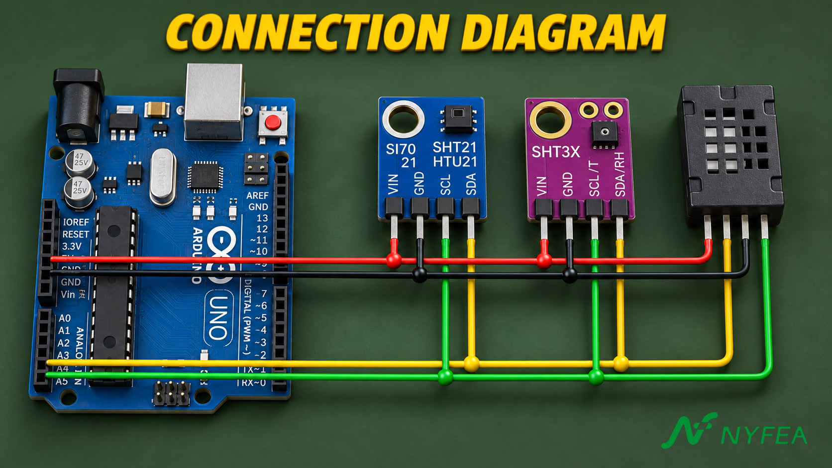
The Arduino host connects its SDA and SCL lines to all three modules and shares a common ground with them. Each device needs its own supply connection at a voltage its installed board supports. Before applying power, verify the host logic voltage and the rail feeding the SDA/SCL pull-up resistors; a shared data bus does not imply that every module can share an unchecked 5 V supply.
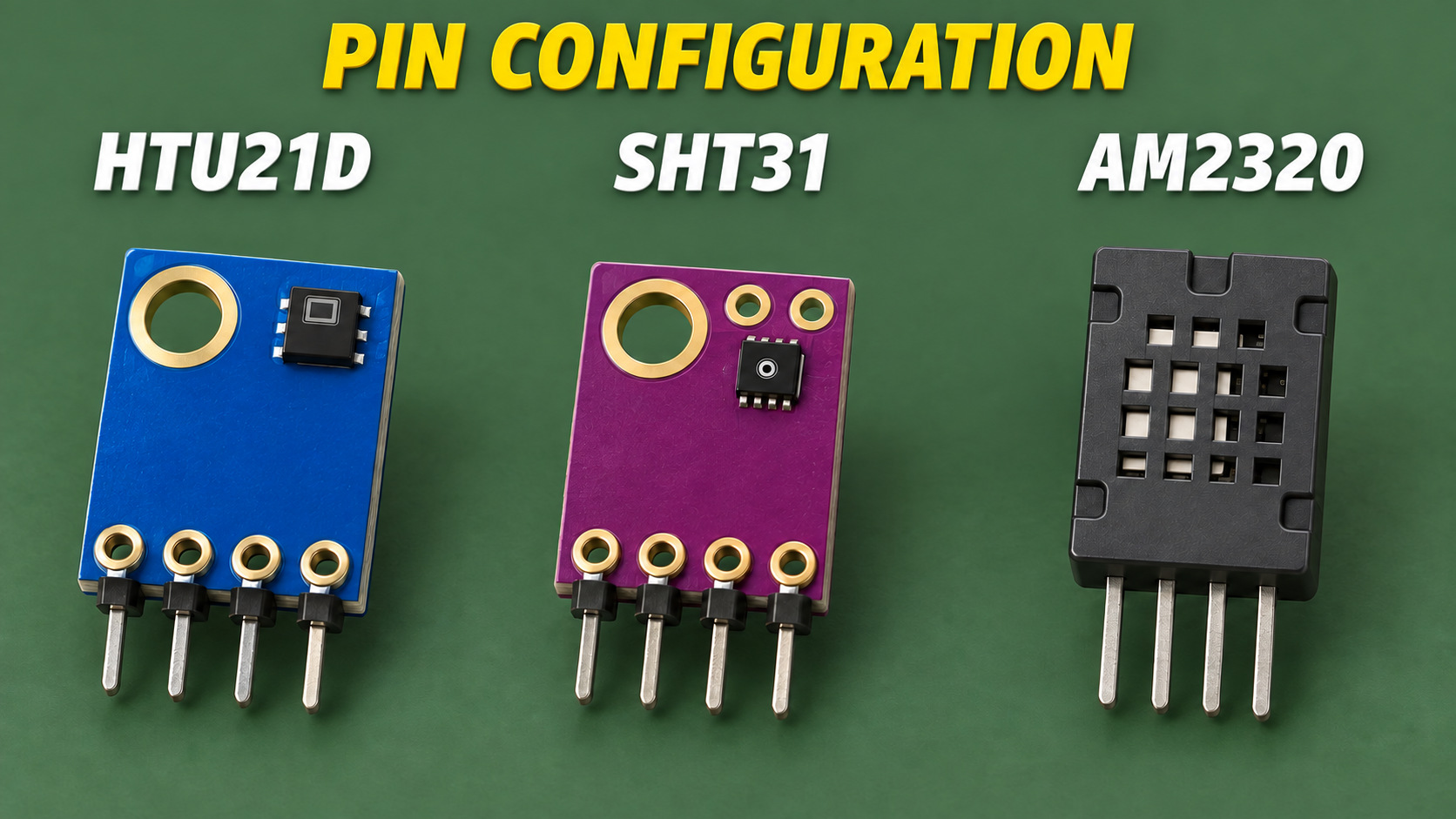
- SHT31: tie ADDR LOW for 7-bit address
0x44or HIGH for0x45; do not leave it floating. - HTU21D: use 7-bit address
0x40. Check the actual breakout schematic because its regulator, if present, does not necessarily protect the SDA and SCL pins. - AM2320: use 7-bit address
0x5C. Its wake behavior and slower sampling interval need their own firmware handling.
Those distinct addresses let the devices coexist, but a scan only establishes communication at an address. The electrical checks and complete reading procedure below determine whether the arrangement is safe and useful.
Functional block diagram of the SHT3x-DIS. The humidity and temperature sensor signals are factory-calibrated and linearized, and are compensated for dependencies on temperature and supply voltage.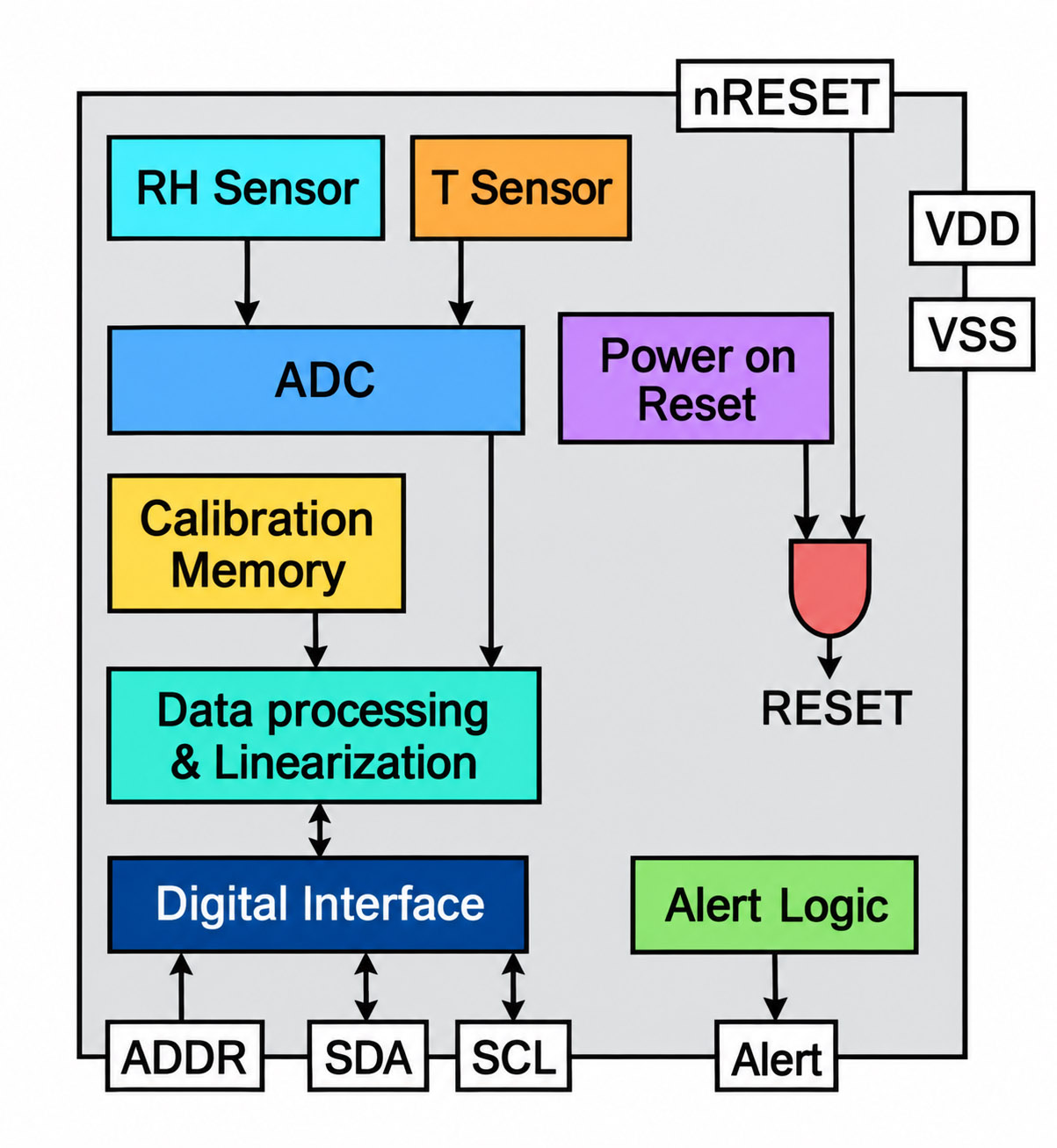
First check the voltage domains
Sensirion specifies SHT31 operation from 2.15 to 5.5 V, while TE lists the HTU21D sensor's normal supply as 1.5 to 3.6 V and a 3.8 V peak. Aosong specifies 3.1 to 5.5 V for AM2320. These ranges describe components, not the entire assortment of third-party modules sold under those names. A 5 V supply or a 5 V SDA/SCL pull-up can exceed the HTU21D chip's limit unless that specific breakout provides a suitable regulator and level translation. A regulator alone does not prove that its signal pins are shifted. SHT3x datasheet; TE sensor range table; AM2320 datasheet.
| Device | 7-bit address | Component supply | Integration question |
|---|---|---|---|
| SHT31 | 0x44 or 0x45 | 2.15–5.5 V | Is ADDR tied to VSS or VDD? It must not float. |
| HTU21D | 0x40 | 1.5–3.6 V; 3.8 V peak listed by TE | Do VCC and SDA/SCL reach the bare chip or a protected breakout? |
| AM2320 | 0x5C | 3.1–5.5 V | Does the host implement the wake and conversion sequence? |
Practical choice: document every board's power path and logic levels, then choose a common bus rail or proper bidirectional level shifting. A nominal 3.3 V rail is within all three listed supply ranges, but AM2320 has only a 0.2 V margin above its 3.1 V minimum; verify the rail at the sensor under worst-case conditions. Check the Arduino host's input-high requirement too. Do not assume a 3.3 V pull-up is always read as HIGH by a 5 V host.
Three checks before applying power
- Confirm each device voltage. Compare the sensor-chip limits with the actual breakout schematic. A board label saying “5 V compatible” does not establish how its sensor and interface are protected.
- Trace the bus HIGH rail. Identify the supply connected to every SDA and SCL pull-up. A regulator on VCC does not necessarily reduce the voltage seen at those signal pins.
- Evaluate the combined pull-ups. Count resistors on the host and all modules, calculate their parallel resistance, then check rise time and LOW-level sink current at the intended bus speed.
Count the pull-ups already on the bus
I²C SDA and SCL are open-drain lines. Several breakout boards may each carry pull-up resistors, while the host or another module adds more. Their parallel combination changes the effective resistance. Three 10 kΩ resistors in parallel produce roughly 3.33 kΩ; two 4.7 kΩ resistors produce about 2.35 kΩ. These are arithmetic examples, not universal recommended values.
Inspect or measure the installed network and record where it pulls: 3.3 V, 5 V, or another rail. Then verify rise time at the intended clock rate and LOW-level sink current using the weakest connected device's limits. A working short cable on a bench may fail after cable length, capacitance or module count changes. Sensirion's datasheet provides the SHT3x I²C electrical constraints; the other devices and the host must also pass.
Scan, wake, read, verify: keep four states separate
Begin at a conservative bus speed supported by all connected devices. Log the 7-bit address and error state rather than treating a scan as the measurement test. SHT31's ADDR input selects 0x44 when tied LOW or 0x45 when tied HIGH; Sensirion says not to leave it floating. AM2320's datasheet also expresses its bus address as the 8-bit write byte 0xB8, corresponding to 7-bit 0x5C. Its wake sequence can make a simplistic scanner or first transaction look like a missing sensor. Follow the documented wake/read timing and avoid polling it faster than its specified measurement interval.
Core diagnostic sequence
- Discover: scan the expected address, record NACK and timeout distinctly.
- Acquire: send the device-specific command and wait for its specified conversion or wake behavior.
- Validate: require the expected byte count; check each device's integrity mechanism, including CRC where provided; reject stale and impossible samples.
- Publish: timestamp a valid sample and keep the prior good value separate from the current failure state.
This state model is more useful than a single sensor.begin() == true flag. It tells a technician whether a fault is electrical, protocol-related, data-integrity related or a genuine environmental mismatch. It also prevents a last-known-good value from masquerading as a new observation.
Decision order: first confirm the device responds at its expected address, then obtain a complete and valid sample with the correct driver, and only then compare its temperature and RH against an independent reference. A scan result alone should never be presented as a sensor accuracy result.
Arduino diagnostic code for all three sensors
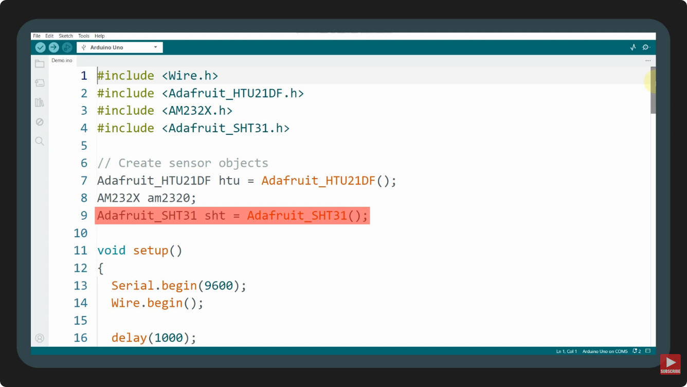
This original example initializes each sensor separately, reads temperature and humidity, and prints a clear error when initialization or acquisition fails. It uses a 100 kHz I²C clock for AM2320 and waits two seconds between readings. Verify breakout voltage and logic levels before running it.
The example uses the documented APIs of the AM232X library,
Adafruit HTU21DF and Adafruit SHT31. Keep device status and NaN checks visible so a failed read is not mistaken for a valid measurement.
// Original NYFEA three-sensor diagnostic example.
// Libraries: Adafruit HTU21DF, Rob Tillaart AM232X, Adafruit SHT31.
// Check each breakout's supply and I2C logic levels before applying power.

#include <Wire.h>
#include <Adafruit_HTU21DF.h>
#include <AM232X.h>
#include <Adafruit_SHT31.h>

Adafruit_HTU21DF htu;
AM2320 am2320;
Adafruit_SHT31 sht;

bool htuReady = false;
bool amReady = false;
bool shtReady = false;

void printPair(const char *name, float tempC, float humidity, bool valid) {
  Serial.print(name);
  Serial.print(F(": "));
  if (!valid || isnan(tempC) || isnan(humidity)) {
    Serial.println(F("read error"));
    return;
  }
  Serial.print(tempC, 2);
  Serial.print(F(" C, "));
  Serial.print(humidity, 2);
  Serial.println(F(" %RH"));
}

void setup() {
  Serial.begin(9600);
  Wire.begin();
  Wire.setClock(100000);  // AM2320 is specified for a 100 kHz bus.
  delay(1000);

  htuReady = htu.begin();
  shtReady = sht.begin(0x44);  // Use 0x45 only when ADDR is tied HIGH.
  amReady = am2320.begin();  // Required by current Rob Tillaart AM232X.

  Serial.println(F("Three-sensor I2C check"));
  Serial.print(F("HTU21D init: "));
  Serial.println(htuReady ? F("OK") : F("FAILED"));
  Serial.print(F("SHT31 init: "));
  Serial.println(shtReady ? F("OK") : F("FAILED"));
  Serial.print(F("AM2320 init: "));
  Serial.println(amReady ? F("OK") : F("FAILED"));
}

void loop() {
  if (htuReady) {
    const float t = htu.readTemperature();
    const float rh = htu.readHumidity();
    printPair("HTU21D", t, rh, true);
  } else {
    Serial.println(F("HTU21D: not initialized"));
  }

  if (amReady) {
    const int status = am2320.read();
    if (status == AM232X_OK) {
      printPair("AM2320", am2320.getTemperature(),
                am2320.getHumidity(), true);
    } else {
      Serial.print(F("AM2320: read error, status "));
      Serial.println(status);
    }
  } else {
    Serial.println(F("AM2320: not initialized"));
  }

  if (shtReady) {
    const float t = sht.readTemperature();
    const float rh = sht.readHumidity();
    printPair("SHT31", t, rh, true);
  } else {
    Serial.println(F("SHT31: not initialized"));
  }

  Serial.println(F("------------------------------"));
  delay(2000);  // Avoid polling AM2320 faster than its sample interval.
}
Keep the AM2320 status code and the NaN checks in the output. A returned number without a valid status should not enter the comparison.
Use the failure pattern to choose the next test
Do not treat every bad value as a calibration problem. Record the first gate that fails, then run the corresponding check.
| Observed symptom | What it establishes | Next useful check |
|---|---|---|
| None of the three addresses responds | No usable bus transaction has been established. | Measure each supply and common ground; inspect SDA/SCL routing, pull-up rail and logic levels before changing sensor code. |
SHT31 acknowledges 0x44 but returns a failed read | The address responded; measurement data are not yet valid. | Check the selected command, conversion delay, complete six-byte frame and the CRC-8 byte following each 16-bit word. A scan alone cannot test those steps. |
| AM2320 NACKs the first transaction or stops updating | A wake transaction may NACK; repeated old values can be mistaken for fresh samples. | Use its documented wake/read sequence, read the returned status and keep at least the specified two-second interval between measurements. . |
| Errors begin after another module or longer cable is added | The bus loading changed, even if the addresses did not. | Recount parallel pull-ups, inspect the HIGH rail and measure rise time at the operating clock before changing a humidity offset. |
| All reads are valid, but RH values differ | Communication is working; accuracy is still unproven. | Log temperature with RH, co-locate the sensing openings, allow equilibrium and swap physical positions before judging the devices. |
CRC is device-specific: SHT31 places CRC-8 after each temperature and RH word; AM2320 uses a different CRC-16 frame. A library's successful begin() result does not replace checking the actual read status.
When three sensors disagree, compare air before comparing brands
Place the sensing openings in the same representative airflow, away from the Uno regulator, display backlight, warm wiring and direct breath. Log temperature and RH together, with timestamps and valid-data flags. Let the assemblies equilibrate after handling, power-up and any enclosure change. A warmer local sensor often reports lower RH even when all devices share the same moisture content; a humidity-only ranking can therefore misidentify a thermal placement issue.
How much can a small temperature difference matter? At unchanged water-vapor partial pressure, air that is 50% RH at 25 °C would be about 44.4% RH at 27 °C, using the saturation-vapor-pressure relation. The roughly 5.6 percentage-point drop is a calculation, not an NYFEA test result or a correction to apply blindly. It shows why a board warmed by a nearby regulator can look “dry” without any change in moisture content.
Use an independent reference if the outcome will support a design decision. Compare repeated stable windows, not a single screenshot of three numbers. Record the reference's uncertainty and the product's allowable error before naming a “winner.” If a device differs, swap its physical position with another device while keeping its electrical channel and code traceable. A position-dependent difference suggests airflow or thermal bias; a device-dependent difference merits calibration, contamination and protocol investigation.
Use this comparison method to separate sensor differences from placement, temperature and firmware effects. Do not infer accuracy from a single set of readings.
Where NYFEA FHT31 belongs in this evaluation
For a design now using SHT31, NYFEA FHT31 is a candidate to evaluate on the same decision path. NYFEA's product specification lists a 2.0–5.5 V supply, selectable 0x44/0x45 addresses and CRC-protected temperature/RH data. Those similarities can simplify a comparison fixture. They do not establish a drop-in replacement. Check pinout, package and land pattern; every firmware command and timing mode; CRC and error recovery; and measured temperature/RH performance in the final enclosure.
If the prototype uses an SHT31 breakout rather than a bare chip, compare the module circuitry separately from the sensor. A direct chip substitution cannot inherit a breakout board's regulator or level shifter. The most useful purchasing request is therefore a small, documented qualification plan with the actual host voltage, bus topology, acceptance limits and environmental test points.
FAQ
Why does an I²C scanner find SHT31 but the humidity reading fails?
The address ACK confirms only bus discovery. Check ADDR wiring, the selected command, conversion wait, complete frame length and CRC before investigating calibration or humidity accuracy.
Can I power all three sensors from an Arduino Uno 5 V pin?
Do not assume so. The bare HTU21D is specified for a lower supply. A particular breakout may contain a regulator or level shifter, but verify its schematic and SDA/SCL voltage before connecting it to a 5 V bus.
Why might AM2320 appear missing on the first scan?
Its documented wake behavior can cause a naive discovery sequence to see a NACK. Use the AM2320 wake and read procedure, distinguish the 7-bit address 0x5C from the 8-bit write byte 0xB8, and respect its sampling interval.
Is FHT31 guaranteed to replace SHT31?
No. Similar address choices and CRC-protected readings make FHT31 a candidate for evaluation. Verify electrical, mechanical, command, timing and final-product measurement behavior before approval.
Source documents
- Sensirion SHT3x-DIS datasheet — SHT31 supply, ADDR and I²C behavior.
- NYFEA FHT31 product specification — candidate scope and limits.