MFRC522 RFID READER DEVELOPMENT · NF522 MIGRATION
MFRC522 RFID Reader with Arduino: Wiring, Code and Troubleshooting
Connect an MFRC522 RFID reader to Arduino over SPI, run a minimal ISO/IEC 14443 Type A test, and isolate card-detection faults. Then determine when NF522 deserves evaluation and which board-level items must be requalified.
DIRECT ANSWER
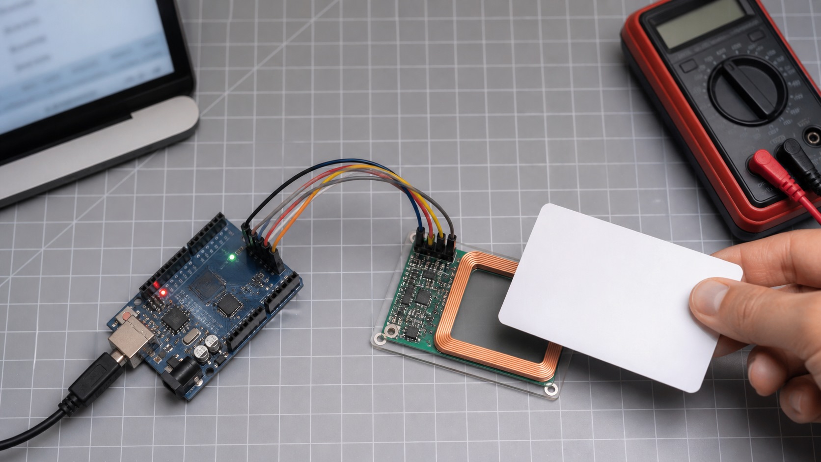
For a common Arduino Uno SPI test, connect the RC522 module’s SDA/NSS to D10, SCK to D13, MOSI to D11, MISO to D12, RST to D9, VCC to 3.3 V and GND to GND. Run a known-good Type A card test before changing hardware. NF522 can then be evaluated as an independent 13.56 MHz migration candidate, but footprint, pins, power, register behavior, RF matching and card performance must be verified; similar package and interface names do not establish drop-in compatibility.
1. What Is the MFRC522? Bare IC vs. RC522 Module
The MFRC522 is a highly integrated 13.56 MHz contactless reader/writer IC whose documented scope covers ISO/IEC 14443 Type A, MIFARE and NTAG. A commonly sold “RC522 module” adds a PCB antenna, matching and filtering components, a 27.12 MHz crystal, decoupling and connectors; some modules also include board-level power circuitry.
A module that does not detect a card therefore does not automatically indicate a failed MFRC522 IC. Likewise, replacing an RC522 module is not equivalent to qualifying a bare-IC board migration.
Record These Items Before Debugging
- Exact module or IC marking, schematic revision and PCB revision;
- MCU, supply voltage, logic voltage and SPI controller;
- Target-card frequency, protocol, UID length and application requirements;
- Antenna dimensions, matching BOM, enclosure, nearby metal and noise sources; and
- Whether the fault occurs at cold start, after wake-up, after enclosure assembly or only with specific cards.
2. MFRC522 Arduino SPI Wiring Example
The following connections apply to a common Arduino Uno SPI setup and a typical RC522 module. Module pin labels, power circuits and logic-level compatibility vary, so the module schematic remains the controlling source.
| RC522 Module | Arduino Uno | Function | Engineering Note |
|---|---|---|---|
| SDA / NSS | D10 | SPI chip select | This is not I²C SDA; the label depends on the module silkscreen. |
| SCK | D13 | SPI clock | Long jumpers and poor contacts can degrade edge integrity. |
| MOSI | D11 | MCU to reader | Confirm signal direction and continuity. |
| MISO | D12 | Reader to MCU | On a shared bus, verify that other devices release MISO. |
| RST | D9 | Reset and power-down control | Do not leave the input asserted low. |
| IRQ | Not required for this polling example | Interrupt output | A production driver may use IRQ, but it must configure and service the signal explicitly. |
| 3.3 V | 3.3 V | Module supply | Do not assume that a bare MFRC522 or an arbitrary module is 5 V tolerant. |
| GND | GND | Signal reference | Use a short, reliable ground connection. |
3. Minimal MFRC522 Type A Reader Code
This example verifies module initialization, card detection, anticollision, selection and UID retrieval. It is a bring-up test, not a secure access-control or payment implementation.
Download the Arduino MFRC522 Baseline Sketch (.ino)#include <SPI.h>
#include <MFRC522.h>
#define RST_PIN 9
#define SS_PIN 10
MFRC522 reader(SS_PIN, RST_PIN);
void setup() {
Serial.begin(115200);
SPI.begin();
reader.PCD_Init();
reader.PCD_DumpVersionToSerial();
Serial.println("MFRC522 reader initialized");
}
void loop() {
if (!reader.PICC_IsNewCardPresent()) return;
if (!reader.PICC_ReadCardSerial()) return;
Serial.print("UID:");
for (byte i = 0; i < reader.uid.size; i++) {
Serial.print(' ');
if (reader.uid.uidByte[i] < 0x10) Serial.print('0');
Serial.print(reader.uid.uidByte[i], HEX);
}
Serial.println();
reader.PICC_HaltA();
reader.PCD_StopCrypto1();
}PCD_Init() initializes the reader. PICC_IsNewCardPresent() performs card detection, while PICC_ReadCardSerial() completes anticollision, selection and UID retrieval. PICC_HaltA() places the selected Type A card in the HALT state.
Security boundary: UID retrieval is useful for bring-up and device-identification demonstrations, but a UID may be copied or emulated. Security-critical access, payment and identity systems require authentication, managed keys, replay protection and a system-level security architecture.
4. What Happens Along the MFRC522 Signal Path?
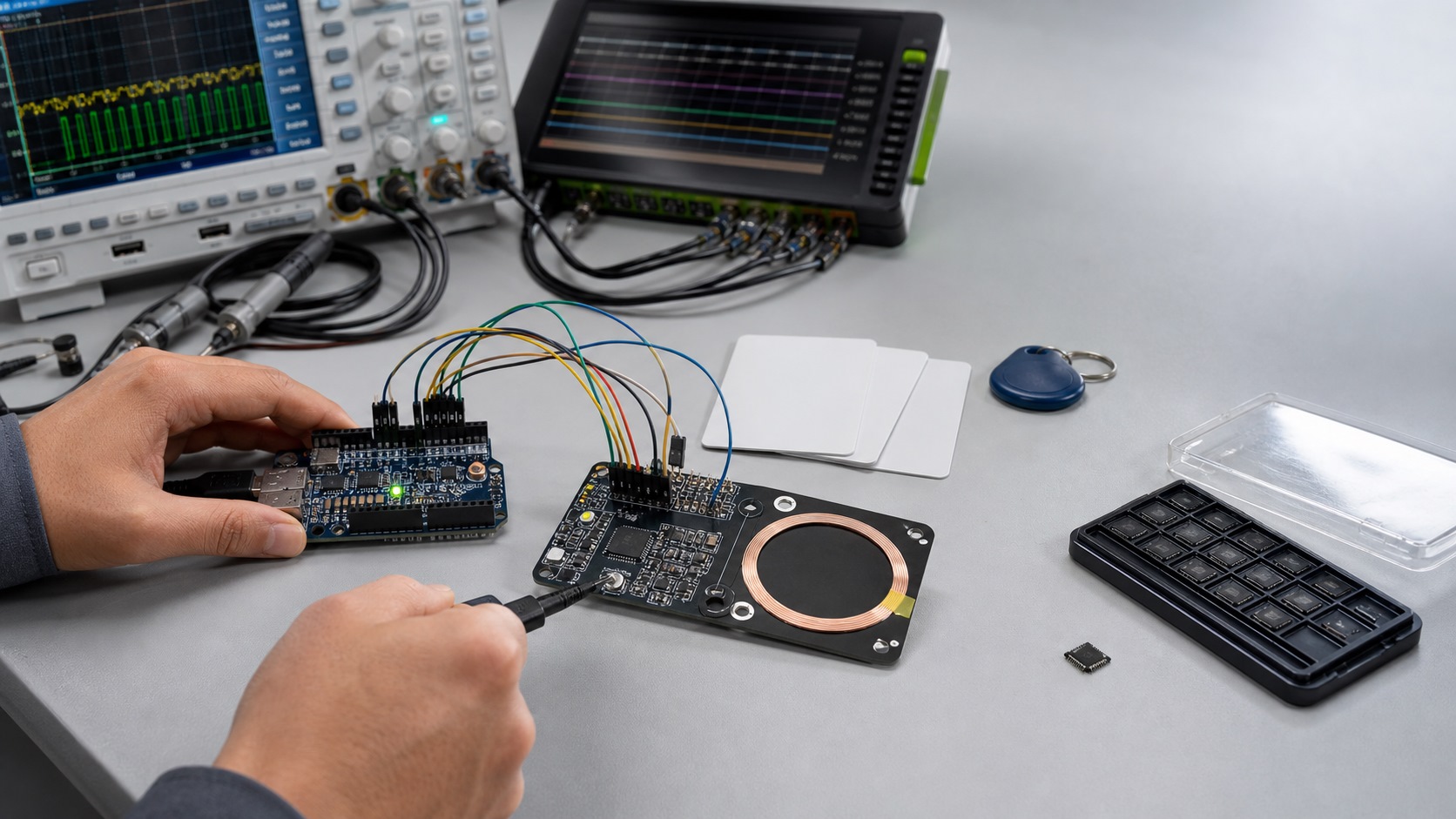
A successful read depends on more than Arduino code. The complete path includes MCU transactions, the reader state machine, the matching network, the antenna magnetic field and coupling to the card.
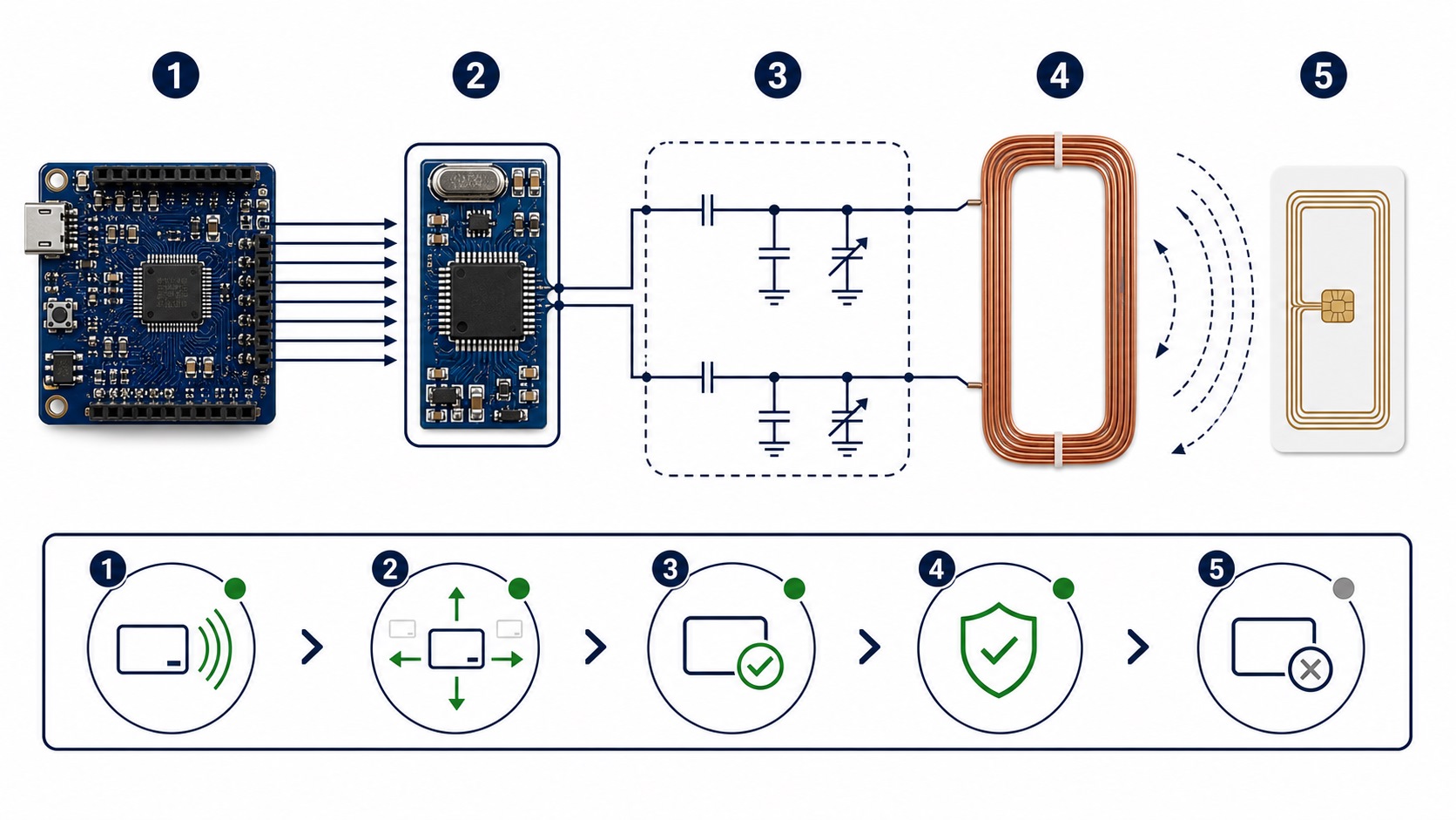
Stable register access proves only part of the digital interface. The presence of a carrier at the antenna does not by itself prove receive sensitivity, modulation quality, protocol handling or target-card interoperability.
5. MFRC522 Not Detecting a Card: Fault Isolation by Layer
| Observed Symptom | Check First | First Useful Measurement |
|---|---|---|
| Firmware Version repeatedly reads 0x00 | Power, reset, chip select, SPI or MISO | Measure supply and RST at the device, then capture CS, SCK, MOSI and MISO. |
| Firmware Version repeatedly reads 0xFF | Open bus, device not selected or device still in reset | Check continuity, the active CS window and MISO direction. |
| Registers are stable, but no card is detected | Command sequence, FIFO, IRQ, RF field or card protocol | Record interrupt, error and FIFO results for one REQA transaction. |
| Only some cards are detected | Frequency, protocol, card antenna and orientation | Establish a control set of cards with documented Type A specifications. |
| Open PCB works, assembled product performs poorly | Metal, ferrite, spacing, noise and detuning | Compare open-PCB, mechanical-assembly and fully operating system states. |
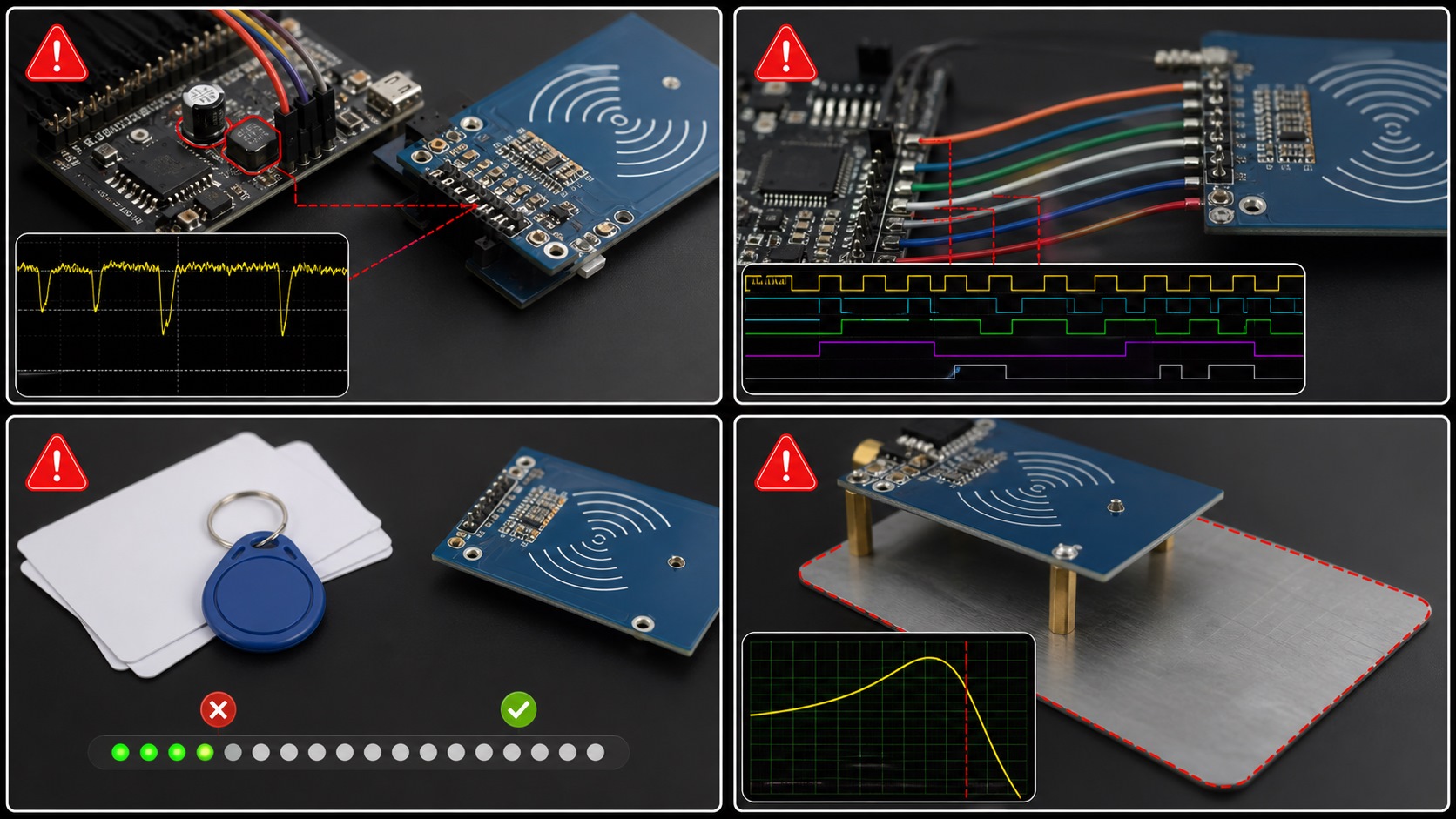
- Confirm the module supply and MCU logic levels.
- Demonstrate repeatable reset and SPI register access.
- Use a test card with a documented ISO/IEC 14443 Type A specification.
- Confirm that the 13.56 MHz field reaches the antenna through the matching network.
- Map the read zone with the final enclosure, metalwork, battery, display and switching converters operating.
For a more detailed fault-isolation procedure, see MFRC522 Not Detecting a Card: Debugging Guide.
6. A Practical MFRC522 Access-Control Prototype
An access-control prototype is more suitable than a transit-payment example for a public engineering guide because it demonstrates the reader workflow without inventing protected keys or transaction infrastructure:
Detect card
  -> Anticollision and select
  -> Read UID or authenticated data
  -> Query local or server-side authorization
  -> Unlock or deny access
  -> Record the event
  -> Halt the card
A production system must also address repeated presentations, rapid card removal, multiple cards in the field, communication timeouts, relay noise, unexpected resets and offline authorization behavior.
7. Why an MFRC522 Design May Need a Second-Source Review
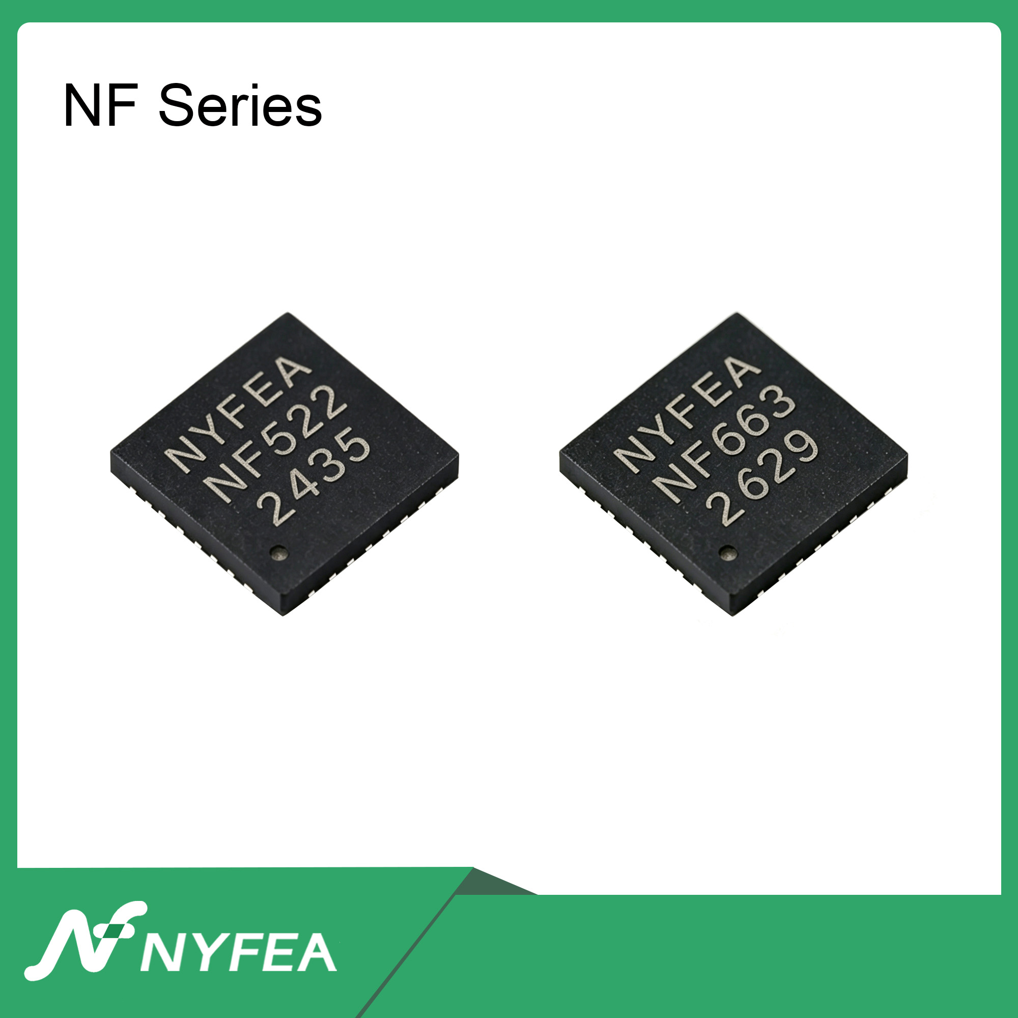
NXP currently marks MFRC52202HN1 as End of Life and states that it is not recommended for new designs; NXP identifies CLRC663 plus as its recommended product for new designs. NF522 is an independent NYFEA product. It is not an NXP-recommended or NXP-endorsed replacement for MFRC522.
NF522 may warrant evaluation when an existing reader requires a lifecycle update, broader protocol coverage, a defined low-power card-detection strategy or a redesigned PCB. The correct question is not whether two product names appear similar, but whether the candidate meets the measured requirements of the complete reader.
8. NF522 vs. MFRC522: Separate Confirmed Facts from Migration Work
| Item | MFRC522 | NF522 | Evidence and Migration Meaning |
|---|---|---|---|
| Carrier frequency | 13.56 MHz | 13.56 MHz | DATASHEET A common frequency does not establish PCB, antenna or firmware compatibility. |
| ISO/IEC 14443 Type A | Supported | Supported | DATASHEET Regression testing with the target card set remains necessary. |
| ISO/IEC 14443 Type B | Not listed in the documented feature scope | Supported | DATASHEET Protocol support does not imply authorization for a specific identity document. |
| ISO/IEC 15693 | Not listed in the documented feature scope | Supported | DATASHEET The host implementation and representative cards still require validation. |
| SPI | Up to 10 Mbit/s | Up to 12 Mbit/s; modes 0 and 3 | VERIFY A shared interface name does not establish transaction compatibility. |
| FIFO | 64 bytes | 64 bytes | VERIFY Commands, status bits, error handling and IRQ behavior may differ. |
| Package | HVQFN32, 5 × 5 mm | QFN32 | PIN REVIEW The same pin count does not establish pin-to-pin compatibility. |
| Registers and Arduino libraries | MFRC522 register set and driver ecosystem | NF522 register set and extended registers | NOT ESTABLISHED No zero-code-change claim is made. |
9. Board-Level Validation from MFRC522 to NF522
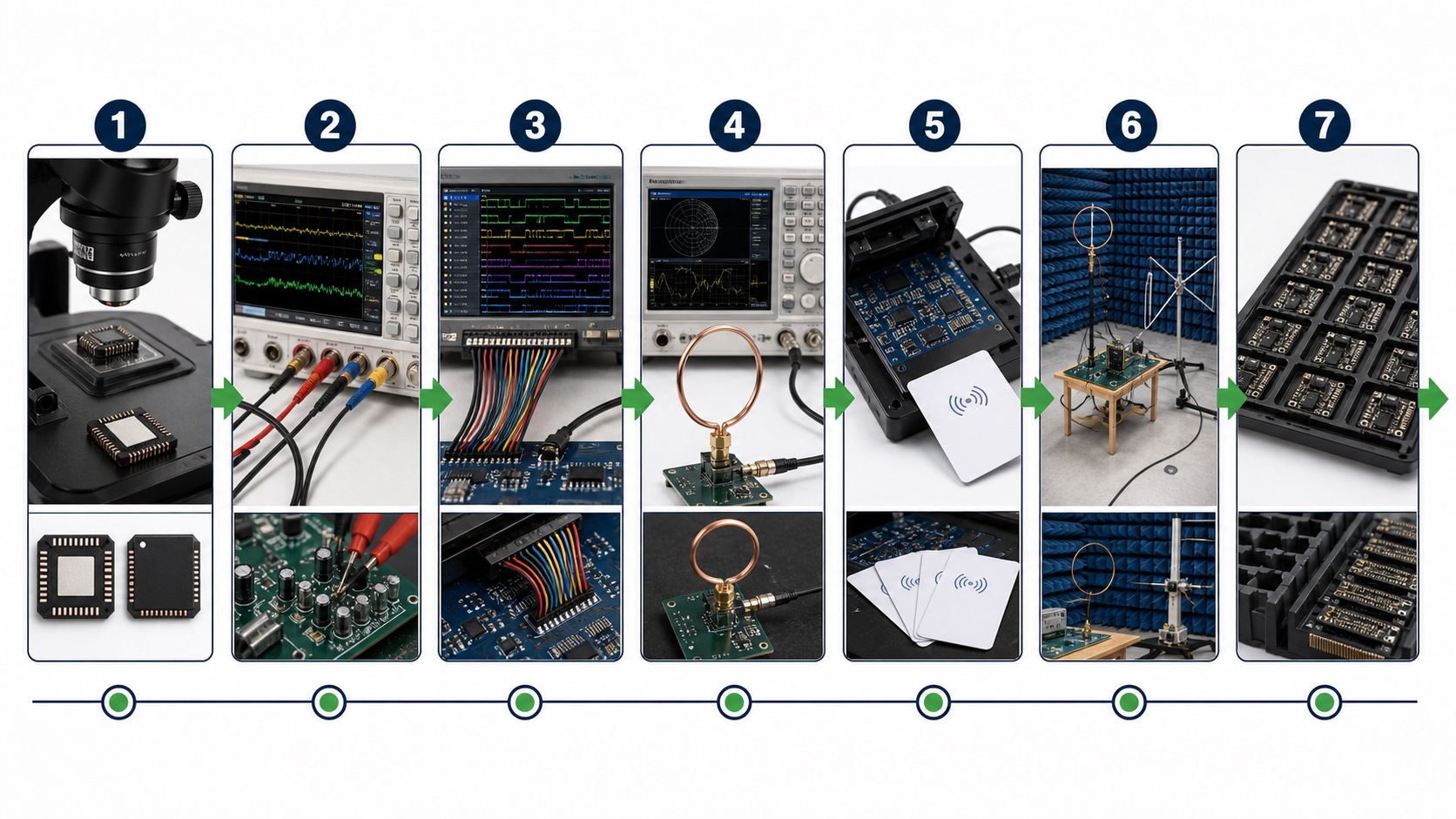
- Freeze the MFRC522 baseline: archive the schematic, PCB, antenna, firmware, card set and measured read-zone data.
- Compare every pin: review supplies, grounds, TX/RX, clock, reset, IRQ, interface selection and exposed pad.
- Compare every power domain: check voltage ranges, sequencing, I/O thresholds, decoupling and field-on current.
- Verify SPI and register behavior: use a logic analyzer to review frame format, mode, addressing, reset values, FIFO and IRQ.
- Remeasure the RF path: the previous antenna is only a starting point; retune and validate it on the NF522 PCB in the final enclosure.
- Regress the target cards: test REQA, WUPA, anticollision, selection, authentication, card removal and error recovery.
- Complete production qualification: cover supply limits, temperature, ESD, EMC, assembly and manufacturing tolerances.
Conclusion: NF522 may be evaluated as a migration candidate for an MFRC522-based 13.56 MHz reader. The actual PCB and software changes can be determined only from the specific design and its validation results.
10. MFRC522 Engineering FAQs
What does an MFRC522 Firmware Version value of 0x00 or 0xFF mean?
A persistent 0x00 usually indicates that no valid register value is being returned. A persistent 0xFF is commonly associated with an open bus, an unselected device or an undriven MISO line. Confirm the cause from power, reset and SPI waveforms rather than replacing the IC based on the value alone.
Why can the MCU read MFRC522 registers but still fail to detect a card?
SPI access proves only part of the digital path. Card detection also requires the correct command, FIFO and IRQ sequence, a usable 13.56 MHz RF field, a matched antenna, a functioning receiver and a supported card.
Can the MFRC522 read 125 kHz tags?
No. MFRC522 is a 13.56 MHz reader IC. A 125 kHz tag requires a reader designed for the corresponding carrier frequency and air interface.
Will an existing MFRC522 Arduino library run on NF522 without modification?
The available technical documentation does not establish this. Upper-layer application logic can inform the migration, but device identification, registers, commands, FIFO, IRQ and RF configuration must be verified.
Can NF522 directly replace MFRC522?
That conclusion cannot be drawn from the product name, carrier frequency, QFN32 package or SPI interface. Footprint and pins, power, host transactions, registers, firmware, RF matching and system-level card performance must all be qualified.
Can the existing MFRC522 antenna be retained?
Its geometry may be retained as a starting point, but the matching components and RF performance cannot be assumed to remain unchanged. Remeasure the antenna on the NF522 PCB with the final enclosure and representative cards.
Evaluating a Second Source or a New MFRC522-Based Design?
Provide the existing schematic, MCU and host interface, power architecture, PCB antenna dimensions, target-card set, enclosure stack, driver and repeatable MFRC522 baseline results. NYFEA Engineering can use this information to define the hardware, firmware and RF validation scope for NF522.