
SHT41 · MULTI-SENSOR DEVELOPMENT
Multiple SHT41 Sensors with ESP32: TCA9548A Wiring and Arduino Code
Your ESP32 reads one SHT41 correctly. Add a second sensor with the same address, and the scanner still reports 0x44. How do you read them separately?
Connect Sensor A to TCA9548A channel 0 and Sensor B to channel 1. Select one channel before each sensor operation. Both sensors remain at 0x44; the multiplexer changes the accessible connection, not the sensor address.
SHT4x is a digital sensor platform for measuring relative humidity and temperature at different accuracy classes. Its I2C interface provides several preconfigured I2C addresses while maintaining an ultra-low power budget (0.4 μW).
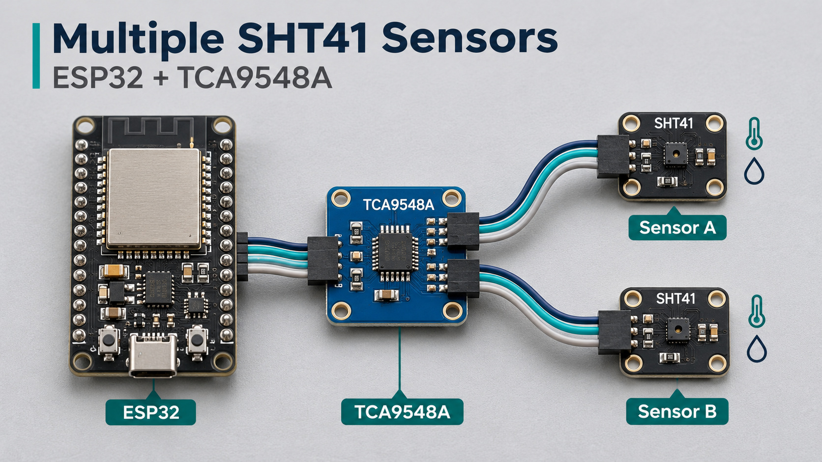
The result should be two identifiable data streams: a known sensor, at a known location, with a fresh reading or an explicit failure status. The example below includes wiring, complete Arduino code and checks that establish that mapping.
Bench setup: classic ESP32 DevKit · Adafruit TCA9548A breakout at
0x70· two Adafruit SHT41 breakouts at0x44· 3.3 V rails · 100 kHz I²C · heater off.
On this page
Why two SHT41 sensors need separate paths
The standard SHT41-AD1B has the 7-bit address 0x44. If two sensors share the same SDA/SCL pair, the ESP32 cannot address them independently. An acknowledgment at 0x44 does not reveal how many devices answered. Sensirion datasheet
Keep these three rules in mind:
- Separate the paths: one
0x44sensor per multiplexer channel. - Select before accessing: initialization, identity reads and measurements must use the intended channel.
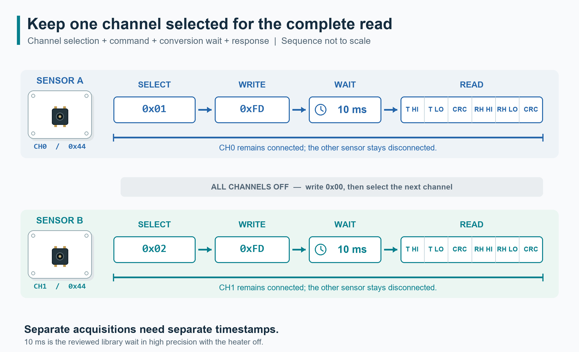
- Keep only that channel enabled: leave it selected through the command, conversion wait and response, then move to the next sensor.
| Identifier | Example | Its job |
|---|---|---|
| Switch address | 0x70 |
Receives channel-selection commands |
| Channel | CH0 or CH1 | Selects a downstream SDA/SCL pair |
| Sensor address | 0x44 on either channel |
Receives the SHT41 commands |
| Serial number | Read separately from each sensor | Identifies the connected device |
Channel number is not the control byte. selectChannel(0) writes 0x01; selectChannel(1) writes 0x02. Writing 0x00 disables all channels. Do not write the channel number directly: 0x03 enables both CH0 and CH1, reconnecting the two same-address sensors. TCA9548A control register
Two software objects alone do not separate the electrical paths. TCA9548A address straps change the switch address, not the SHT41 addresses. TI switch documentation
Prepare a simple two-sensor setup
Use short bench wires, soldered headers and one supply. Leave other I²C devices and wireless networking out of the first test. The named breakouts matter: generic boards may use different regulators, pull-ups or pin labels.
Connect power and the upstream bus
Make all wiring changes with power disconnected.
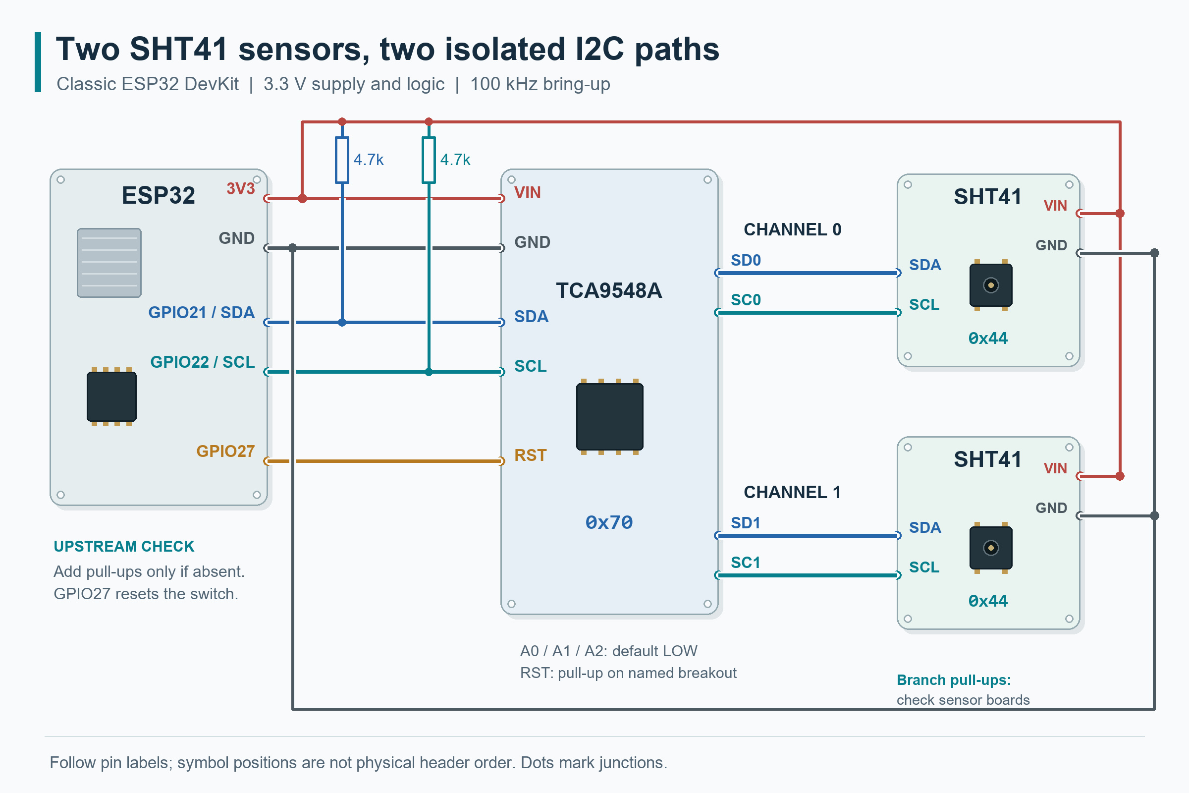
| ESP32 | Connect to |
|---|---|
3V3 |
TCA9548A VIN and both SHT41 breakout VIN pins |
GND |
All three breakout GND pins |
| GPIO21 | TCA9548A upstream SDA |
| GPIO22 | TCA9548A upstream SCL |
| GPIO27 | TCA9548A RST |
Use 3.3 V supply and logic rails throughout. Leave the named Adafruit SHT41 board's 3Vo regulator output unconnected. A breakout VIN rating does not change the bare sensor's voltage limit. Sensor board pinouts
These GPIO assignments are for the classic ESP32 example. Check and change them for other ESP32 boards. Arduino-ESP32 I²C API
Put each sensor on one channel
| TCA9548A | Sensor |
|---|---|
SD0 / SC0 |
Sensor A SDA / SCL |
SD1 / SC1 |
Sensor B SDA / SCL |
Match the suffixes: SD0 belongs with SC0. Do not also connect a sensor's SDA/SCL to the upstream bus. Both sensors share power and ground; deselecting a channel does not turn its sensor off.
Check pull-ups and reset once
- Upstream SDA/SCL: add pull-ups if absent. For a short 3.3 V bench setup, 4.7 kΩ per line is a starting choice to verify electrically.
- Downstream branches: the Adafruit TCA9548A board has no downstream pull-ups; check those fitted to each sensor board.
- RST: the named switch board holds it HIGH through a pull-up. Confirm that another board's reset connection is compatible with GPIO27 at 3.3 V.
A selected branch connects its pull-ups to the upstream path. Check the effective resistance and signal quality before adding more resistors. Multiplexer board pinouts
Prove each layer before adding the next
Test each SHT41 alone first. If either fails the single-sensor ESP32 example, fix that failure before adding the switch.
After assembling the multiplexed circuit, the sketch checks the paths in this order:
| Check | Expected result | If it fails |
|---|---|---|
Switch at 0x70 |
Acknowledgment | Check upstream wiring, supply, reset and address straps |
| All channels off | No acknowledgment at 0x44 |
Check for an upstream bypass or ineffective isolation |
| CH0 selected | Sensor A initializes and returns a serial number | Test its module and branch separately |
| CH1 selected | Sensor B returns a different serial number | Check channel selection and branch routing |
The sketch probes these two addresses; this table describes expected results, not captured measurements.
The staged approach matters: a two-SHT41 forum project involved both a faulty multiplexer and a later initialization problem.
Complete Arduino code for two SHT41 sensors
Each acquisition follows select channel → command → conversion wait → validated read → deselect. Keep that whole operation on the same channel. Other tasks must not change the switch halfway through it.
In Arduino IDE, install Adafruit SHT4x Library, Adafruit BusIO and Adafruit Unified Sensor. Select your ESP32 board and open Serial Monitor at 115200 baud. Record the Arduino-ESP32 core and library versions with your project so the setup can be reproduced.
Before uploading, check three settings:
- Pins:
SDA_PIN,SCL_PINandMUX_RST_PINmatch the circuit. - Switch address:
MUX_ADDRmatches its address straps. - Node table: each channel has one location label, initially
point_aandpoint_b.
Code review status: checked against the linked library source; compilation and physical-board operation still need verification on your setup.
The library validates measurement CRCs. The additional identity helper reports serial-read success separately from the serial value. Driver implementation
#include <Wire.h>
#include <Adafruit_SHT4x.h>
#include <math.h>

constexpr int SDA_PIN = 21;
constexpr int SCL_PIN = 22;
constexpr int MUX_RST_PIN = 27;
constexpr uint8_t MUX_ADDR = 0x70;
constexpr uint8_t SHT_ADDR = 0x44;
constexpr uint32_t PERIOD_MS = 2000;

struct Node {
  uint8_t channel;
  const char *location;
  bool ready;
  uint32_t serial;
};

Node nodes[] = {
  {0, "point_a", false, 0},
  {1, "point_b", false, 0}
};
constexpr size_t NODE_COUNT = sizeof(nodes) / sizeof(nodes[0]);
Adafruit_SHT4x sensors[NODE_COUNT];
bool running = false;
uint32_t previousCycle = 0;

void resetMux() {
  digitalWrite(MUX_RST_PIN, LOW);
  delay(1);
  digitalWrite(MUX_RST_PIN, HIGH);
  delay(1);
}

bool writeMux(uint8_t mask) {
  Wire.beginTransmission(MUX_ADDR);
  Wire.write(mask);
  return Wire.endTransmission() == 0;
}

bool selectChannel(uint8_t channel) {
  if (channel > 7) return false;
  return writeMux(static_cast<uint8_t>(1U << channel));
}

bool acknowledges(uint8_t address) {
  Wire.beginTransmission(address);
  return Wire.endTransmission() == 0;
}

uint8_t wordCrc(uint8_t first, uint8_t second) {
  uint8_t crc = 0xFF;
  const uint8_t bytes[2] = {first, second};
  for (uint8_t value : bytes) {
    crc ^= value;
    for (uint8_t bit = 0; bit < 8; ++bit) {
      crc = (crc & 0x80)
          ? static_cast<uint8_t>((crc << 1) ^ 0x31)
          : static_cast<uint8_t>(crc << 1);
    }
  }
  return crc;
}

// Caller must select the intended channel first.
bool readSerialChecked(uint32_t &serial) {
  Wire.beginTransmission(SHT_ADDR);
  Wire.write(0x89);
  if (Wire.endTransmission() != 0) return false;
  delay(10);
  if (Wire.requestFrom(SHT_ADDR, static_cast<size_t>(6)) != 6) {
    while (Wire.available()) Wire.read();
    return false;
  }
  uint8_t data[6];
  for (uint8_t &value : data) value = Wire.read();
  if (wordCrc(data[0], data[1]) != data[2] ||
      wordCrc(data[3], data[4]) != data[5]) return false;
  serial = (static_cast<uint32_t>(data[0]) << 24) |
           (static_cast<uint32_t>(data[1]) << 16) |
           (static_cast<uint32_t>(data[3]) << 8) | data[4];
  return true;
}

void stopAfterBusFault() {
  running = false;
  resetMux();  // Hardware reset attempts to isolate downstream branches.
  Serial.println("BUS_FAULT: mux reset; inspect wiring, then restart ESP32");
}

void setup() {
  Serial.begin(115200);
  delay(300);
  digitalWrite(MUX_RST_PIN, HIGH);
  pinMode(MUX_RST_PIN, OUTPUT);
  resetMux();

  if (!Wire.begin(SDA_PIN, SCL_PIN, 100000)) {
    Serial.println("STOP: ESP32 I2C initialization failed");
    return;
  }
  Wire.setTimeOut(50);
  if (!acknowledges(MUX_ADDR) || !writeMux(0)) {
    Serial.println("STOP: check mux power, reset, address and upstream bus");
    return;
  }
  if (acknowledges(SHT_ADDR)) {
    Serial.println("STOP: 0x44 visible with all channels off; check topology");
    return;
  }

  for (size_t i = 0; i < NODE_COUNT; ++i) {
    Node &node = nodes[i];
    if (!selectChannel(node.channel)) {
      stopAfterBusFault();
      return;
    }
    const char *status = "NO_SENSOR_ACK";
    if (acknowledges(SHT_ADDR)) {
      status = "INIT_FAIL";
      if (sensors[i].begin(&Wire)) {
        sensors[i].setPrecision(SHT4X_HIGH_PRECISION);
        sensors[i].setHeater(SHT4X_NO_HEATER);
        node.ready = readSerialChecked(node.serial);
        status = node.ready ? "READY" : "SERIAL_READ_FAIL";
      }
    }
    Serial.printf("BOOT,ch=%u,location=%s,status=%s",
                  node.channel, node.location, status);
    if (node.ready) {
      Serial.printf(",serial=%08lX", static_cast<unsigned long>(node.serial));
    }
    Serial.println();
    if (!writeMux(0)) {
      stopAfterBusFault();
      return;
    }
  }

  for (size_t i = 0; i < NODE_COUNT; ++i) {
    if (!nodes[i].ready) continue;
    for (size_t j = 0; j < i; ++j) {
      if (nodes[j].ready && nodes[i].serial == nodes[j].serial) {
        Serial.println("STOP: duplicate identities; verify channel routing");
        return;
      }
    }
  }
  for (const Node &node : nodes) running = running || node.ready;
  if (!running) {
    Serial.println("STOP: no sensor passed initialization and identity checks");
    return;
  }
  Serial.println("ms,ch,location,serial,temp_C,rh_pct,status");
}

void loop() {
  if (!running || millis() - previousCycle < PERIOD_MS) return;
  previousCycle = millis();

  for (size_t i = 0; i < NODE_COUNT; ++i) {
    Node &node = nodes[i];
    if (!node.ready) {
      Serial.printf("%lu,%u,%s,-,-,-,NOT_INITIALIZED\n",
                    static_cast<unsigned long>(millis()),
                    node.channel, node.location);
      continue;
    }
    if (!selectChannel(node.channel)) {
      stopAfterBusFault();
      return;
    }

    sensors_event_t humidity{}, temperature{};
    const bool valid = sensors[i].getEvent(&humidity, &temperature) &&
                       isfinite(temperature.temperature) &&
                       isfinite(humidity.relative_humidity);
    Serial.printf("%lu,%u,%s,%08lX,",
                  static_cast<unsigned long>(millis()), node.channel,
                  node.location, static_cast<unsigned long>(node.serial));
    if (valid) {
      Serial.printf("%.2f,%.2f,OK\n",
                    temperature.temperature, humidity.relative_humidity);
    } else {
      Serial.println("-,-,READ_FAIL");
    }
    if (!writeMux(0)) {
      stopAfterBusFault();
      return;
    }
  }
}
Interpret the status first
| Status | Meaning / action |
|---|---|
READY |
Initialization and identity read succeeded; confirm the location mapping |
NO_SENSOR_ACK |
Check that branch's wiring, power and pull-ups |
INIT_FAIL / SERIAL_READ_FAIL |
The sensor acknowledged but a later startup operation failed; test it alone and restart after repair |
NOT_INITIALIZED |
Startup checks failed for this node; after repair, restart the ESP32 to initialize it |
READ_FAIL |
Reject this sample; the next cycle retries the initialized node |
BUS_FAULT |
A switch transaction failed; reset was attempted and acquisition stopped for inspection |
READ_FAIL does not identify whether the command, receive operation or CRC check failed. The library combines those outcomes into one failure flag.
The two-second cycle reads sensors sequentially, not simultaneously. The ms column is completion time in ESP32 uptime; it resets at reboot and eventually wraps. Use a persistent clock or server timestamp for long-term records.
Confirm that the readings belong to the right sensor
Look for one READY entry per connected node and this data header:
ms,ch,location,serial,temp_C,rh_pct,status
A successful row has a fresh reading; a failed row has a status and no measurement number. Similar readings do not prove a wiring mistake, and different readings do not prove correct routing. Check the mapping directly:
- Record both serial numbers and label the cables.
- Power down and disconnect B from CH1, then restart. A should be
READY; CH1 should remain unavailable. - Restore B and disconnect A, with power off, then restart. The result should reverse.
- Reconnect both and restart. Each serial number should return to its original channel.
An OK row confirms a CRC-valid transfer, not measurement accuracy. Serial numbers establish identity, not authenticity or calibration accuracy; two displayed decimal places do not establish two-decimal-place accuracy.
Invalidate a failed sample immediately. If rows stop arriving entirely, the receiving logger or controller must expire its cached value after a timeout chosen for the application. A last-known value must not remain a current control input indefinitely.
Troubleshoot the symptom you actually see
| Symptom | First discriminating check |
|---|---|
No 0x70 acknowledgment |
Check switch power, common ground, upstream SDA/SCL, RST and address straps |
| One branch fails | Check its SDn/SCn pair, power, pull-ups and solder joints |
0x44 responds with all channels off |
Look for a sensor wired upstream or a switch-control problem |
| Duplicate sensor identity | Confirm channel selection and eliminate upstream bypasses |
Intermittent READ_FAIL |
Record the channel; check supply at the module, contacts and selected-path signal quality |
| Selecting one branch stalls communication | Check whether that branch holds SDA or SCL LOW |
| Valid frames but unexpected temperature/RH | Check placement, local heat and airflow separately from communication |
To localize a fault, power down and swap the sensor modules while leaving branch wires in place. A fault following the module points toward that module or its headers; one staying on the channel points toward the branch or switch port.
A stuck bus needs more than another read attempt
Writing 0x00 deselects channels during normal communication. A branch holding SDA/SCL LOW may prevent that write. Hardware RST can deselect the branches independently of an I²C command, but it does not power-cycle or repair the sensor. TI reset behavior
This bring-up sketch resets the switch and stops after a switch transaction failure. For unattended use, add bounded recovery attempts, upstream-bus checks and per-branch isolation. Test that policy on the actual circuit rather than assuming that one healthy sensor always remains accessible.
Turn two working channels into useful measurements
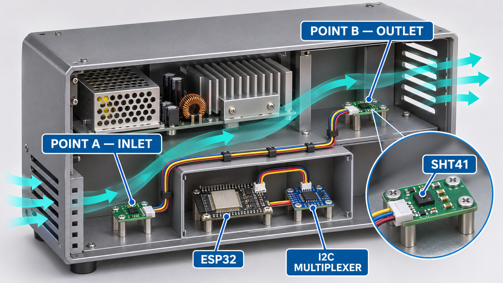
Start with two nearby points, such as a small cabinet's air inlet and outlet. Keep the channel–serial–location record when installing or moving cables.
Compare in the same airflow
- Co-locate both sensors, away from the ESP32 and supply components, and allow them to settle.
- Compare several complete cycles, rather than one pair of readings.
- This establishes initial agreement; neither sensor is automatically a reference for the other.
Trace an unexpected difference
After installation, swap sensors between locations:
- Difference follows the location: investigate environment or mounting effects.
- Difference follows the sensor: compare it against a suitable calibrated reference.
Look for a repeatable pattern. Set the acceptable difference from the application error budget and reference uncertainty, rather than a universal pass threshold. See the enclosure and airflow guide.
Read temperature and RH together
Lower outlet RH alone does not prove moisture removal. RH also depends on temperature. Decide which physical quantity your application needs before interpreting the difference.
Add channels without changing the basic method
The TCA9548A has eight channels, 0–7. For a third sensor, connect SD2/SC2 and add {2, "point_c", false, 0} to nodes, keeping commas between entries. The sketch derives the node count and checks identities across initialized nodes. TI documentation
Recheck four things as the system grows:
- Timing: sequential readings have different acquisition times.
- Signal quality: validate the longest selected path and its pull-ups.
- Power: all modules stay powered; heater operation needs separate power and thermal checks.
- Access ownership: every task must respect channel selection.
Keep the initial 100 kHz clock; the TCA9548A ceiling is 400 kHz, even if the sensor supports a faster bus. A switch also does not turn I²C into a long-distance link. For distant locations, consider local nodes or an appropriately engineered buffered/differential connection.
Before using the readings in a controller
- Identity: each location maps to the intended sensor.
- Freshness: failed or missing samples cannot appear current.
- Failure handling: branch loss and bus faults produce a deliberate response.
- Measurement: final mounting and enclosure conditions have been checked.
Frequently asked questions
How do I connect multiple SHT41 sensors to one ESP32?
Connect the SHT41 sensors to separate TCA9548A channels, with one same-address sensor per channel. In this example, CH0 carries Sensor A and CH1 carries Sensor B; both retain the 7-bit address 0x44. Select the intended channel before initialization, serial-number reads and measurements. Keep it selected throughout the command, conversion wait and six-byte response, then deselect it before moving on.
Can I change the SHT41 address instead?
The standard SHT41-AD1B uses 0x44 and has no documented user address-change command. Changing the TCA9548A address straps changes only the switch address, not either sensor address. Confirm the complete sensor ordering code before choosing an alternative circuit; address options offered by other SHT4x models do not establish SHT41 behavior. Sensirion datasheet
Why does 0x70 appear on every selected channel?
The TCA9548A at 0x70 stays on the upstream bus, so its acknowledgment can appear regardless of the selected channel. With CH0 or CH1 enabled, this circuit should also expose one downstream SHT41 at 0x44. With all channels disabled, 0x44 should disappear. If it remains visible, inspect upstream bypass wiring and channel control. An address scan alone cannot identify which sensor answered.
Can I select both channels and read both sensors together?
No—not as independent readings when both sensors use 0x44. The TCA9548A permits multiple channels to be enabled, but that reconnects both same-address sensors to the bus. Write a one-channel mask: 0x01 for CH0 or 0x02 for CH1, rather than 0x03 for both. The example reads the sensors sequentially; it does not provide simultaneous sampling. TI control-register documentation
Why do both channels report nearly identical readings?
Similar temperature and RH values can be normal when both sensors experience the same air. They do not establish correct routing. Read and record each sensor's serial number, then power down and disconnect one branch before restarting. Confirm that only its channel becomes unavailable. Repeat for the other branch; this distinguishes a real two-sensor mapping from accidentally accessing one sensor twice.
How many SHT41 sensors can one TCA9548A support?
One TCA9548A provides eight channels, numbered 0–7, allowing up to eight same-address SHT41 sensors with one on each channel. Add each channel and location to the example's node table, and keep channel entries unique. More sensors lengthen the sequential scan; verify selected-path pull-ups, wiring and power. The switch's 400 kHz maximum and eight-channel count do not establish acceptable cable length or simultaneous sampling. TI datasheet
Can I use PCA9546A instead?
A PCA9546A can provide separate paths, but it has four channels, 0–3, rather than the TCA9548A's eight. Verify the exact breakout's supply, reset, address straps and pull-ups before adapting this circuit. Restrict channel selection and node-table entries to that device's range; the example's TCA9548A range check alone would still accept channels 4–7. NXP datasheet
Selecting sensors for a custom multi-point board
NYFEA FHT41 can enter a new-board sensor evaluation. Compare controlled electrical, interface, package and measurement requirements; this SHT41 sketch does not establish FHT41 firmware or footprint compatibility.
Technical references
- Sensirion SHT4x datasheet — address, identity and CRC.
- TI TCA9548A datasheet — switch, reset and electrical limits.
- Adafruit multiplexer pinouts — named breakout wiring.
- Adafruit SHT4x driver — library behavior.
- Arduino-ESP32 I²C API — pins and timeout configuration.