SHT41 Sensor Datasheet Explained: Pinout, Accuracy and I2C
Sensirion's SHT41 is a digital relative-humidity (RH) and temperature sensor. Its specifications are included in the SHT4x family datasheet. Use the SHT41 entries and your complete ordering code when checking a circuit, driver or accuracy requirement.
Open the official SHT41 / SHT4x datasheet PDF
Reference: SHT4x v7.3, June 2026. The bare SHT41-AD1B is the baseline here; a breakout board's power circuitry needs a separate check.
Choose the part of the guide that matches your task:
- Checking a design? Start with the specification table, then the PCB and assembly checks.
- Connecting a sensor? Use the pinout and wiring checks.
- Getting failed or unusual readings? Follow the measurement sequence, then the accuracy checks.
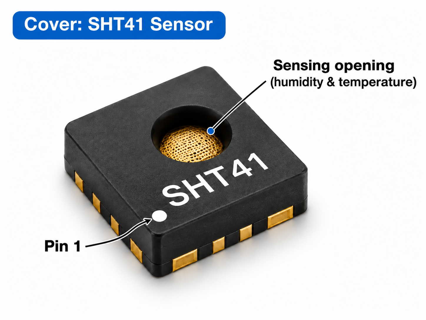
SHT41 specifications at a glance
Use this table for a first design check. The value and its conditions belong together. Official SHT41 product information
| Item | SHT41 value | Condition or design boundary |
|---|---|---|
| Typical RH accuracy | ±1.8 %RH | The 25 °C curve has this value over 30–70 %RH; check Figure 7 separately for typical RH/temperature tolerance |
| Typical temperature accuracy | ±0.2 °C | A typical value; read Figure 11 for the limit at your operating temperature |
| Bare-chip supply | 1.08–3.6 V | Check the chip supply and the allowed SDA/SCL levels; a module's VIN rating is separate |
| RH measurement range | 0–100 %RH | Does not imply uniform accuracy or unrestricted exposure |
| Temperature measurement range | −40 to +125 °C | Does not make the headline accuracy valid throughout that range |
| 7-bit I²C address | 0x44 | SHT41-AD1B-R2 and SHT41-AD1B-R3 |
| Recommended normal conditions | 5–60 °C, 20–80 %RH | Check Section 2.3 for prolonged exposure outside this range |
| Nominal AD1B package | 1.5 × 1.5 × 0.5 mm | Use the selected option's drawing, tolerances and land pattern |
For a maximum RH-error requirement, use the maximum curve, rather than the typical figure. At 25 °C, Figure 3 gives ±2.5 %RH over 0–90 %RH and a rising limit above that region. Figure 7 is a typical RH/temperature map, not a maximum-limit map. SHT4x datasheet, Section 2
Confirm the part before choosing the driver
For SHT41-AD1B-R2 and SHT41-AD1B-R3, the ordering table specifies the 7-bit address 0x44. Check other complete ordering codes individually. SHT4x datasheet, Table 12
Record three things together:
- Hardware: the supplier's complete part number and the module revision.
- Software: the driver or component name and its version.
- Connection: the bus, controller pins and detected address.
An address is not a model identifier. If software labels the installed SHT41 as another sensor, verify the part and driver before changing formulas or delays. A historical Meshtastic report illustrates this failure path; its outcome depends on the firmware version.
Check the module's documentation as well as the chip marking. A working scan is the next observation to make, followed by the full measurement below.
Connect the SHT41 with the correct pin orientation
The SHT41 communicates over I2C, using SDA for data and SCL for clock. The bare-chip pins are:
| Pin | Name | Connection |
|---|---|---|
| 1 | SDA | I2C data |
| 2 | SCL | I2C clock |
| 3 | VDD | Sensor supply |
| 4 | VSS | Ground |
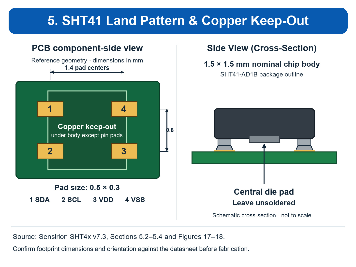
Figure 18 is a transparent top view. Match the pin-1 indicator before comparing it with a PCB bottom view or a module connector. SHT4x datasheet, Section 5.4
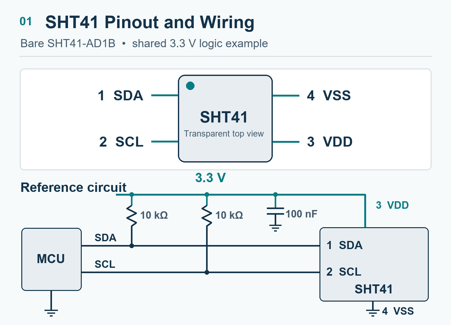
For a first connection, check the schematic rather than relying on cable color:
- Follow the supply path. Identify whether the connector feeds the chip directly or passes through a regulator.
- Follow SDA and SCL. Identify their pull-up supply and any level shifting.
- Check local support components. Compare decoupling and pull-ups with the reference circuit and the connected boards.
- Check orientation and continuity. Do this with power disconnected before the first read.
A module's VIN rating belongs to that board. It does not change the bare sensor's supply rating. For a 5 V host or an unfamiliar breakout, use the SHT41 power and logic-level guide to review both rails before connecting them.
Read and validate one SHT41 measurement
For the initial SHT41-AD1B check, use 7-bit address 0x44, write 0xFD, allow 10 ms, and read six bytes. Accept the temperature/RH pair only after both cyclic redundancy checks (CRCs) pass.
- Send the commandWrite
0xFDto0x44(7-bit). - Read the responseWait 10 ms in this example, then read six bytes.
- Validate and convertCheck both CRCs, then convert the raw temperature and humidity words.
This matches the acquisition path in Sensirion's embedded driver. The 10 ms delay is its blocking implementation's wait, not the sensor's environmental response time.
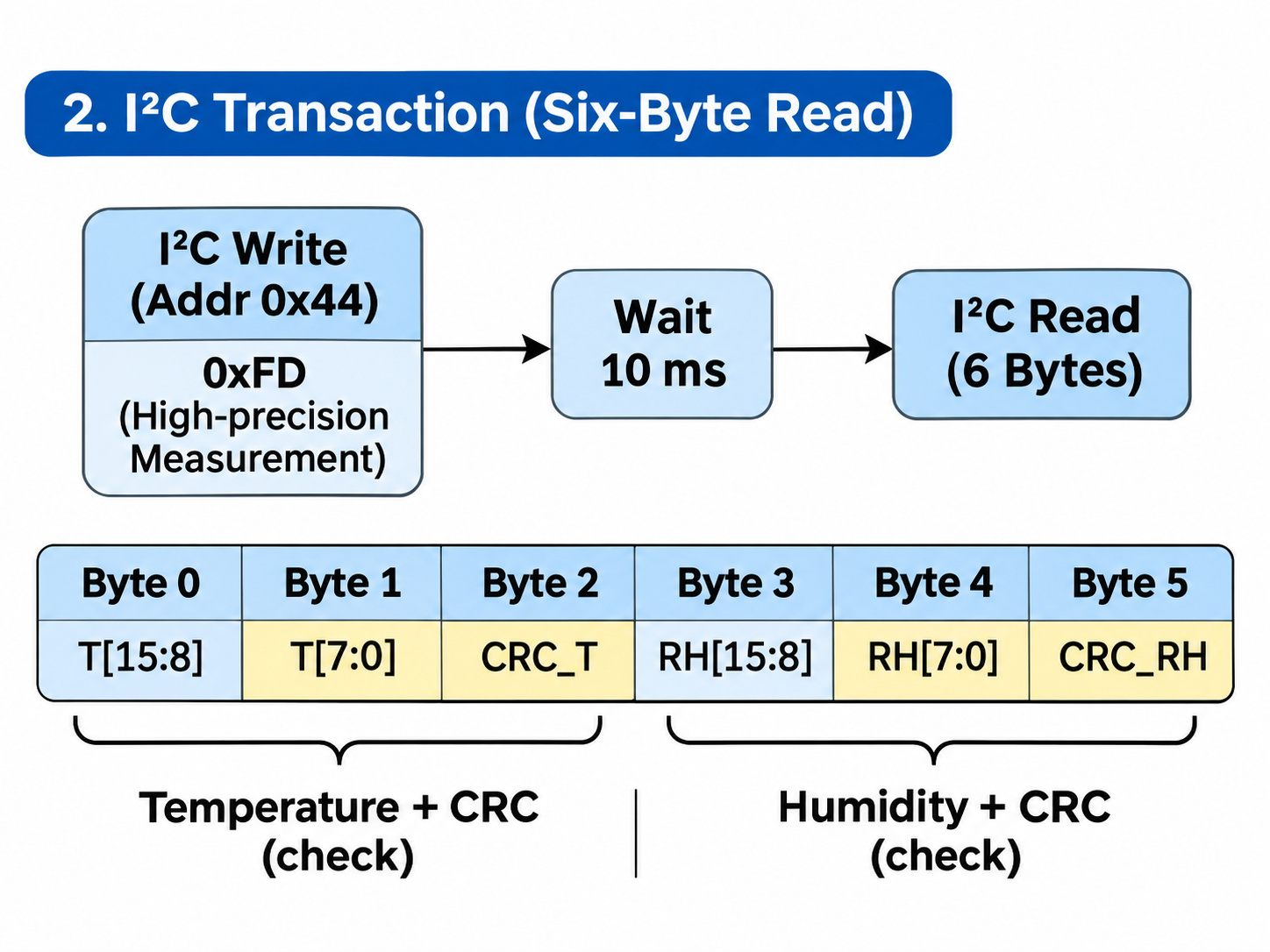
| Response bytes, counted from zero | Contents | Validation |
|---|---|---|
| 0–1 | Temperature word, most-significant byte first | Compare its CRC with byte 2 |
| 3–4 | RH word, most-significant byte first | Compare its CRC with byte 5 |
Use CRC-8, polynomial 0x31, initial value 0xFF, separately for each word. One CRC over the entire response is incorrect. The official I2C helper shows the per-word check.
After both checks pass, assemble and convert the raw words. Here, MSB means most-significant byte and LSB means least-significant byte:
raw_T  = 256 × T_MSB  + T_LSB
raw_RH = 256 × RH_MSB + RH_LSB

temperature_C = −45 + 175 × raw_T  / 65535
humidity_RH   =  −6 + 125 × raw_RH / 65535
These are the datasheet's conversion equations. Keep intermediate arithmetic wide enough and preserve the fractional calculation. For presentation, limit RH to 0–100 %RH; retain the unmodified result separately if investigating boundary behavior. SHT4x datasheet, Section 4.6
Why can a scan succeed while the read fails?
A successful scan confirms an address response, not a complete measurement. An Orange Pi developer reported fixing this symptom by changing the Python multi-byte read implementation.
Find the last step that worked. Then use the corresponding check below.
| Observation | Next check |
|---|---|
| No address acknowledgment | Check sensor power and ground, the selected host bus, SDA/SCL routing and pull-ups. |
| Address scan succeeds, but the measurement command fails | Check that the host writes one command byte, 0xFD, to the SHT41-AD1B at 7-bit address 0x44. |
| Command write succeeds, but the read fails | Use the 10 ms example wait and request six bytes in a plain I²C read. Check whether the host API sends an unintended register byte. |
| Read is short or either CRC fails | Capture the raw bytes. Check the requested length, byte order and bus signal integrity. Start a new acquisition after an incomplete read. |
| Both CRCs pass, but temperature or humidity looks wrong | Check the raw-word conversion first. Then compare with a suitable reference to check placement, airflow and board heating. |
For Python code, inspect whether the selected API sends a register/command byte before reading. Do not assume a parameter named register=0 means “send nothing.” Compare the resulting bus operation with the required sequence.
The SHT41 can return NACK, meaning no acknowledgment, when read while busy; it does not support clock stretching to hold the host while it finishes. Its response is consumed by the first acknowledged read header. After an incomplete read, restart a defined acquisition. SHT4x datasheet, Section 4.1
For complete platform code, continue with the Arduino ESP32 guide or STM32F407 HAL guide.
Portable C example for SHT41 acquisition
Show portable C acquisition and logging code
Write 0xFD to the 7-bit address 0x44, wait 10 ms, then read all six bytes. This heater-off example checks temperature and humidity separately and updates the output only when both CRCs pass. The transaction and conversion follow the SHT4x datasheet and the timing used in the Sensirion embedded driver.
Implement the three board_* functions for your platform. Use a plain I²C read, and allow the sensor to complete startup before the first command. If the host API returns a success code instead of a byte count, translate it in the adapter. For example, map STM32 HAL_OK to the requested byte count, and apply any address shift the HAL requires there.
#include <stddef.h>
#include <stdint.h>

/* Implement these three functions for your board.
 * I2C addresses are 7-bit. Return transferred byte count, or -1 on error.
 * Each write ends with STOP. Reads do not send a register byte.
 * Use finite I2C timeouts. delay_ms must wait AT LEAST the requested time.
 */
int board_i2c_write(uint8_t addr7, const uint8_t *data, size_t count);
int board_i2c_read(uint8_t addr7, uint8_t *data, size_t count);
void board_delay_ms(uint32_t milliseconds);

typedef enum {
    SHT41_OK = 0,
    SHT41_BAD_ARGUMENT,
    SHT41_WRITE_FAILED,
    SHT41_READ_FAILED,
    SHT41_SHORT_READ,
    SHT41_T_CRC_FAILED,
    SHT41_RH_CRC_FAILED
} Sht41Status;

typedef struct {
    float temperature_c;
    float rh_unclipped;
    float rh_display;
} Sht41Sample;

static uint8_t sht41_crc_word(const uint8_t *word)
{
    uint8_t crc = 0xFFu;
    unsigned byte, bit;
    for (byte = 0; byte < 2u; ++byte) {
        crc ^= word[byte];
        for (bit = 0; bit < 8u; ++bit) {
            unsigned next = (unsigned)crc << 1;
            if ((crc & 0x80u) != 0u) {
                next ^= 0x31u;
            }
            crc = (uint8_t)next;
        }
    }
    return crc;
}

Sht41Status sht41_read_sample(Sht41Sample *out)
{
    const uint8_t addr7 = 0x44u, command = 0xFDu;
    uint8_t frame[6];
    uint16_t raw_t, raw_rh;
    Sht41Sample sample;
    int received;

    if (out == NULL) {
        return SHT41_BAD_ARGUMENT;
    }
    if (board_i2c_write(addr7, &command, 1u) != 1) {
        return SHT41_WRITE_FAILED;
    }
    board_delay_ms(10u);
    received = board_i2c_read(addr7, frame, sizeof frame);
    if (received < 0) {
        return SHT41_READ_FAILED;
    }
    if (received != (int)sizeof frame) {
        return SHT41_SHORT_READ;
    }
    if (sht41_crc_word(frame) != frame[2]) {
        return SHT41_T_CRC_FAILED;
    }
    if (sht41_crc_word(frame + 3) != frame[5]) {
        return SHT41_RH_CRC_FAILED;
    }
    raw_t = (uint16_t)(((uint16_t)frame[0] << 8) | frame[1]);
    raw_rh = (uint16_t)(((uint16_t)frame[3] << 8) | frame[4]);
    sample.temperature_c = -45.0f + 175.0f * (float)raw_t / 65535.0f;
    sample.rh_unclipped = -6.0f + 125.0f * (float)raw_rh / 65535.0f;
    sample.rh_display = sample.rh_unclipped;
    if (sample.rh_display < 0.0f) sample.rh_display = 0.0f;
    if (sample.rh_display > 100.0f) sample.rh_display = 100.0f;
    *out = sample;  /* No output changes on any failure path. */
    return SHT41_OK;
}
Call the following function periodically from one task after bus initialization. Add it below the core, supply the monotonic millisecond clock, and route printf to your logging output. Each failed attempt reports the failing stage and, when available, how old the last valid sample is. The next poll starts a new measurement command.
#include <stdbool.h>
#include <stdio.h>

/* Application hooks: a monotonic millisecond clock and a working log output.
 * Compile this example after the core above; map printf to your logger.
 */
uint32_t app_millis(void);

void sht41_poll_and_log(void)
{
    static const char *const names[] = {
        "ok", "bad_argument", "write_failed", "read_failed",
        "short_read", "temperature_crc_failed", "humidity_crc_failed"
    };
    static Sht41Sample last_good;
    static uint32_t last_valid_ms;
    static bool have_valid;
    Sht41Sample candidate;
    Sht41Status status = sht41_read_sample(&candidate);
    uint32_t now = app_millis();

    if (status == SHT41_OK) {
        last_good = candidate;
        last_valid_ms = now;
        have_valid = true;
        printf("fresh T=%.2f C RH=%.2f %%RH\n",
               (double)last_good.temperature_c, (double)last_good.rh_display);
    } else if (have_valid) {
        printf("error=%s last_valid_age_ms=%lu; no new sample\n",
               names[status], (unsigned long)(now - last_valid_ms));
    } else {
        printf("error=%s; no valid sample yet\n", names[status]);
    }
}
Decide which accuracy limit your application needs
For an SHT41 design, select the applicable error limit before comparing readings or adding a correction. These four terms answer different questions:
- Accuracy: how close is the result to an appropriate reference under the specified conditions?
- Repeatability: how much do repeated results vary when conditions are held constant?
- Resolution: how small a change can the output represent?
- Response: how quickly does the sensor approach a changed condition?
A stable display with extra decimal places does not establish absolute accuracy. Sensirion's specification statement explains these distinctions.
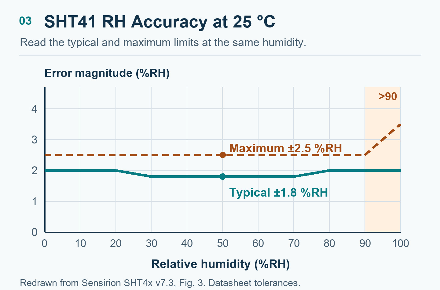
Worked design screen — illustrative, not test results. Suppose a finished device must stay within ±3 %RH at 25 °C and 50 %RH. Assigning the SHT41 component's ±2.5 %RH maximum to a simple additive worst-case budget leaves 0.5 %RH for other system contributions. Using the ±1.8 %RH typical number would leave an unjustified larger allowance.
That calculation screens the design; it does not establish a passing measurement. Choose a reference and an acceptance rule that account for test uncertainty, then validate the installed device.
Why does the SHT41 read warmer and drier after the board warms up?
If the SHT41 reads warmer and drier as the board warms up, check for a local heat source before applying a correction. Warmer air has a lower relative humidity at the same water vapor pressure. Board heat can therefore shift both readings even when the surrounding room air stays stable. Sensirion design guide, Section 3
On the Adafruit SHT41 Trinkey, the SAMD21 sits near the middle of the board. The SHT41 sits near a cutout at the opposite end from USB. Use the layout to trace two paths from a nearby heat source. Adafruit SHT41 fabrication drawing · EagleCAD files
Through the boardHeat can reach the sensor pads through the PCB. A cutout can reduce conduction along this path.
Through the airAir can pick up heat from nearby electronics before reaching the sensor opening. Check airflow with the enclosure fitted.
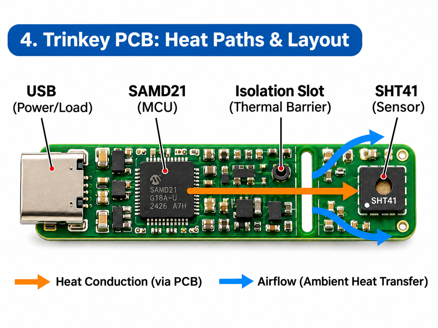
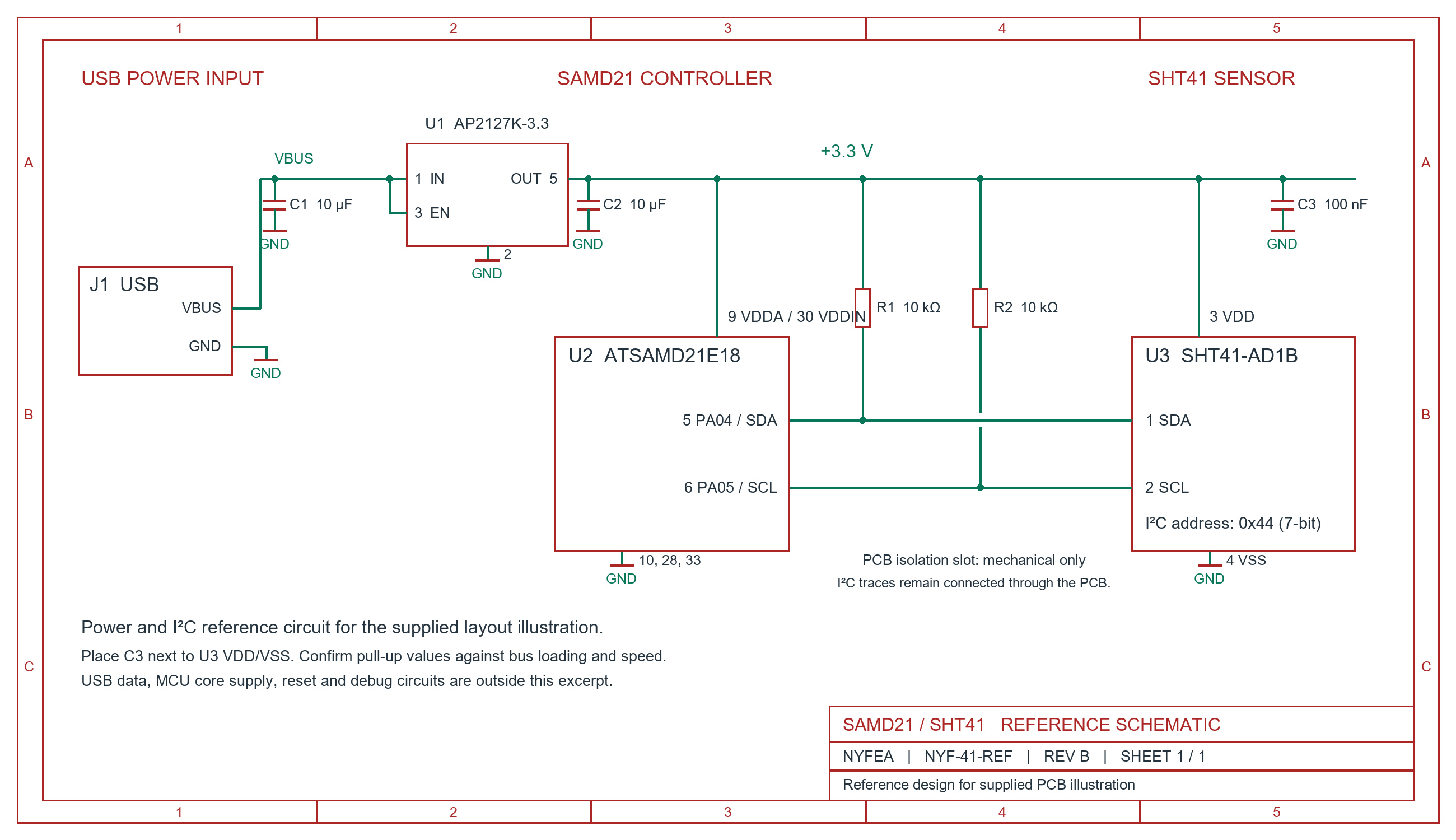
Test the effect of controller load. Keep the SHT41 heater off. Keep the enclosure, airflow, sampling rate and reference position fixed.
- Idle. Place a suitable reference in the air the product is intended to measure, away from direct board heating. Let both readings settle and log temperature and RH.
- Active. Increase controller load. Once the readings settle, log both devices again.
- Idle again. Restore the original load and check whether the difference returns to its starting value. Keep timestamps for all three stages.
Sensirion guide to testing at ambient conditions
- The difference grows under load and shrinks at idle. Review heat transfer from the electronics. Repeat with one change to sensor placement or airflow to see which change reduces the gap.
- Both devices track the same change. Check whether the sampled air itself changed during the run before attributing the shift to the PCB.
- The difference stays roughly constant. Verify the reference and the test conditions across the intended operating range before choosing an offset.
Use the finished device's accuracy budget to judge the residual difference. The Trinkey drawing shows a layout choice. The load comparison shows whether the difference tracks board activity. To separate PCB conduction from warm airflow, keep the load fixed and change one design factor at a time.

Choose a measurement mode and budget its current
The SHT41 mode trades conversion duration and repeatability against current. A mode called “high precision” does not turn the SHT41 into a different absolute-accuracy class.
| Repeatability mode | Command | Maximum conversion duration | Typical average current |
|---|---|---|---|
| High | 0xFD | 8.3 ms | 2.2 µA |
| Medium | 0xF6 | 4.5 ms | 1.2 µA |
| Low | 0xE0 | 1.6 ms | 0.4 µA |
The averages apply to one measurement per second, heater off. The durations are Table 5 maxima, including power-up; see its characterization conditions. These figures are not instantaneous measurement current or whole-module current. SHT4x datasheet, Tables 4–5 and 8
Conversion time is not environmental response time. The first tells software when to request data; the second describes the sensor following a change in its surroundings. Table 1 gives an RH response time of 4 s to reach 63% of a humidity step, measured at 25 °C and 1 m/s airflow. The installed sensor can respond more slowly. Faster polling alone cannot establish that it has settled.
For battery planning, draw the whole acquisition-and-transmission cycle. Include the controller, radio, regulator and module indicators, then measure current at the battery input over that cycle. A sensor-only average cannot establish product runtime.
When can a heater sample be used?
An SHT41 heater sample must be identified separately from an ambient sample. CRC validity checks transmission integrity; normal measurement specifications do not apply during heating. Sensirion's heater application note separates heating, thermal equilibration and subsequent reading.
A MicroPython example returns values from the heater function before taking a later ordinary sample. Its waiting time is an example, not a universal recovery requirement.
Before enabling heating:
- Check power. Table 4 lists 100 mA maximum for the nominal 200 mW heater setting; budget the selected setting separately from µA measurement averages.
- Label samples. Log heating and recovery states, and exclude them from ordinary ambient reporting as appropriate.
- Validate recovery. Repeat under the intended temperature and airflow conditions in the final enclosure.
Use the heater limits in datasheet Section 4.9 and Table 4 when defining the routine.
Check the PCB and assembly process before acceptance
For an SHT41 PCB, review the land pattern as well as the package outline. Sensirion advises against soldering the central die pad and specifies no copper beneath the sensor except at its pin pads. SHT4x datasheet, Section 5.3
What if RH changes immediately after soldering?
A changed RH reading immediately after soldering needs a process-history check before a verdict. Developers have raised this post-assembly question, and Sensirion's handling instructions, Section 2 describe a possible temporary negative RH offset after high-temperature exposure.
Record the process, elapsed time, storage conditions and comparison setup. Apply the relevant conditioning and testing instructions. A procedure for a bare sensor is not automatically suitable for a populated module, and a persistent offset still needs investigation.
What can cleaning and enclosure materials change?
Keep the SHT41 sensing opening free of coating and review chemical exposure. The manufacturer's instructions address adhesives, material emissions and board washing. Handling instructions, Sections 1.3–2
A DigiKey packaging discussion shows why this matters: an unexplained RH shift after processing needs a review of materials and conditions. The thread does not prove a particular contamination mechanism. Check the actual enclosure, adhesive and cleaning process before adjusting firmware.
Before approving the assembly, retain:
- The ordering code, footprint revision and driver version.
- The verified supply and pull-up rails.
- Error records and the sampling/heater policy.
- Comparison results with a suitable reference in the intended operating states.
- The assembly, conditioning and material-exposure record.
Set acceptance limits from the application requirement and the measurement system's uncertainty. Sensirion's ambient-testing guide explains why the fixture and procedure need their own capability assessment. A successful room-temperature check does not qualify every operating condition.
Frequently asked questions
Does every SHT41 include a sensor-specific calibration certificate?
The SHT41 is factory calibrated. That does not mean every ordering option includes an individual calibration certificate. Verify the supplied documentation against the exact part number when a certificate is a purchasing requirement. Official SHT41 product information
Does the SHT41 use a conventional register map?
SHT41 measurement, serial-number and reset operations use commands listed in Section 4.5. Do not substitute an arbitrary register address when a host API requests one. Consult the official command table. For unreliable transfers, the long-I2C-cable guide separates transaction checks from electrical-path checks.
Can two SHT41 sensors be connected to one controller?
One controller can read multiple SHT41 sensors when each is independently accessible. Two same-address SHT41-AD1B parts need separate paths, such as multiplexed channels or separate host buses. One address in a scan does not count sensors. See the multiple-SHT41 guide.
Can the SHT41 measure above 80% RH continuously?
The SHT41 measures up to 100 %RH. Sensirion recommends 20–80 %RH for normal operation. Prolonged exposure above the recommended range can temporarily shift the RH reading. Validate any sustained high humidity use under the intended conditions and check recovery before setting the product's accuracy claim. SHT4x datasheet, Section 2.3
Why does an I²C capture show 0x88 or 0x89 instead of 0x44?
SHT41-AD1B uses the 7-bit address 0x44. The address byte on the wire also contains the read/write bit, so it appears as 0x88 for writes and 0x89 for reads in tools that display the full byte. Pass 0x44 to a host API that expects a 7-bit address.
How can I reset one SHT41 without issuing a bus-wide reset?
Send the 0x94 soft-reset command to the address of the accessible SHT41, then allow 1 ms for reset before the next command. On a multiplexer, select the target channel first. The I²C general-call reset can affect other devices on the same accessible bus.
How do I read the SHT41 serial number for production traceability?
Send the 0x89 serial-number command and read two 16-bit words, each followed by its own CRC byte. Validate both words and store the resulting serial number alongside the board identifier in the production log.
How can I check my SHT41 CRC routine without a sensor?
Feed the routine the two bytes 0xBE and 0xEF in that order. The datasheet gives the expected CRC as 0x92. This check verifies the calculation against a known input. Test frame handling separately by corrupting the temperature CRC and humidity CRC in turn.
Primary technical references
- Sensirion SHT4x datasheet, v7.3, June 2026 — device-specific limits, drawings and interface requirements.
- Sensirion embedded SHT4x driver — measurement and CRC implementation.
- Sensor Specification Statement and Testing Guide — interpretation of specifications.
- Design Guide for Humidity and Temperature Sensors, v2, March 2024 — installation and thermal paths.
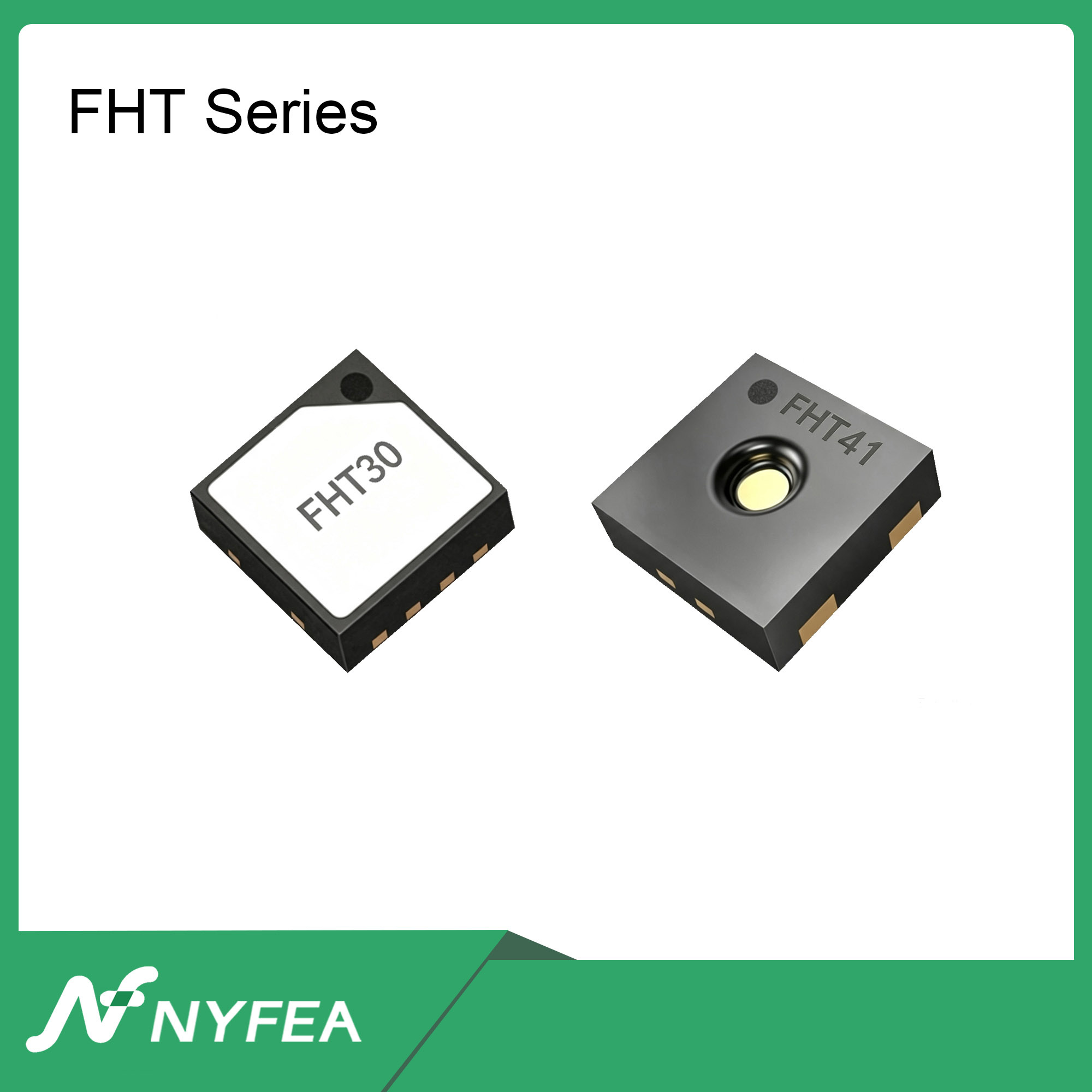
Sensirion and SHT41 identify the original manufacturer's product. NYFEA FHT41 is an independent product; references here do not imply affiliation or verified interchangeability.
Evaluating a sensor for your own PCB?
Bring the supply rails, host platform, temperature/RH range and allowed measurement error to the selection review. For a new PCB, evaluate NYFEA FHT41 against its own controlled specifications, then validate the assembly. This SHT41 guide does not establish interchangeability.