SHT41 Dew Point Calculation for HVAC Condensation
Technical review pending
Calculate dew point from valid Sensirion SHT41 air-temperature and relative-humidity readings, then compare it with a separate measurement of the HVAC surface temperature. The calculator accepts °C or °F and reports the condensation margin. For a new air-side sensing board or second-source review, evaluate NYFEA FHT41 against the same measurement requirements. A grille can collect moisture when it reaches or drops below the dew point of the air touching it. ASHRAE guidance on surface condensation
Calculate dew point and condensation margin
Example. At 26 °C and 70% RH, the estimated dew point is 20.1 °C. A grille at 18 °C is 2.1 °C below that dew point, so condensation is possible there. The readings in this example are illustrative. Vaisala dew point equation
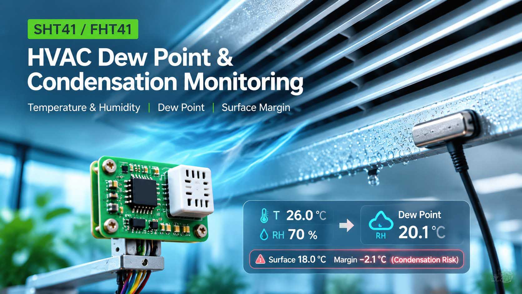
How do you calculate dew point from SHT41 readings?
SHT41 provides temperature and relative humidity; the host calculates dew point from that pair. Use measurements from one completed acquisition and record their timestamp. Enter those values in the calculator, together with a surface-probe reading taken in the same interval. SHT4x data format and conversion
- Acquire and validate a complete sample. For a high-repeatability SHT41 measurement, send
0xFD, wait for conversion, and read six bytes in order: two temperature bytes, their CRC, two humidity bytes and their CRC. Reject the sample if either CRC check fails. The datasheet quick-start example waits 10 ms before reading. SHT4x quick-start sequence and command table - Use the correct units. Combine each pair of data bytes with the first byte as the most significant byte. Let ST be the unsigned 16-bit temperature word and SRH the humidity word. Calculate
T = −45 + 175 × ST / 65535in °C andRH = −6 + 125 × SRH / 65535in percent. Limit converted RH to 0–100%. The calculator requires RH above 0%. If your driver already returns °C and % RH, use those readings with the matching temperature unit selected. SHT4x signal conversion - Check sample age and location. Record failures, timestamps and heater activity. Use a current sample from the air reaching the selected surface. Mark an expired reading as unavailable, and set the allowed age from the application’s sampling interval and rate of change. SHT41 measurement and CRC guide
- Verify recovery after heating. The SHT41 heater command samples while the heater is still on, even though the result is read after it switches off. Exclude that result from ambient dew point calculations. Resume with a fresh unheated measurement after the assembled sensor meets your recovery criterion against an independent air reference in the actual airflow. Record the elapsed time and criterion. SHT4x heater guidance, Section 4.9
Check the assembled sensor with the host idle and under normal load, keeping the air reference in the same place. If the temperature and RH shift with board load, compare the calculated dew point with the reference before applying a correction. Investigate airflow and heat from the board if the results diverge. A valid CRC verifies data integrity. The reference helps assess whether the reading represents the air at the surface. PCB heat and enclosure test method
Where should you place sensors for HVAC condensation checks?
Measure air temperature and RH where the air actually reaches the surface you want to keep dry. At a supply grille, the relevant air can come from the room or a nearby gap. Start at the wet edge and record which side of the grille you sampled. A wall thermostat reading is only a useful substitute when it represents that same air.
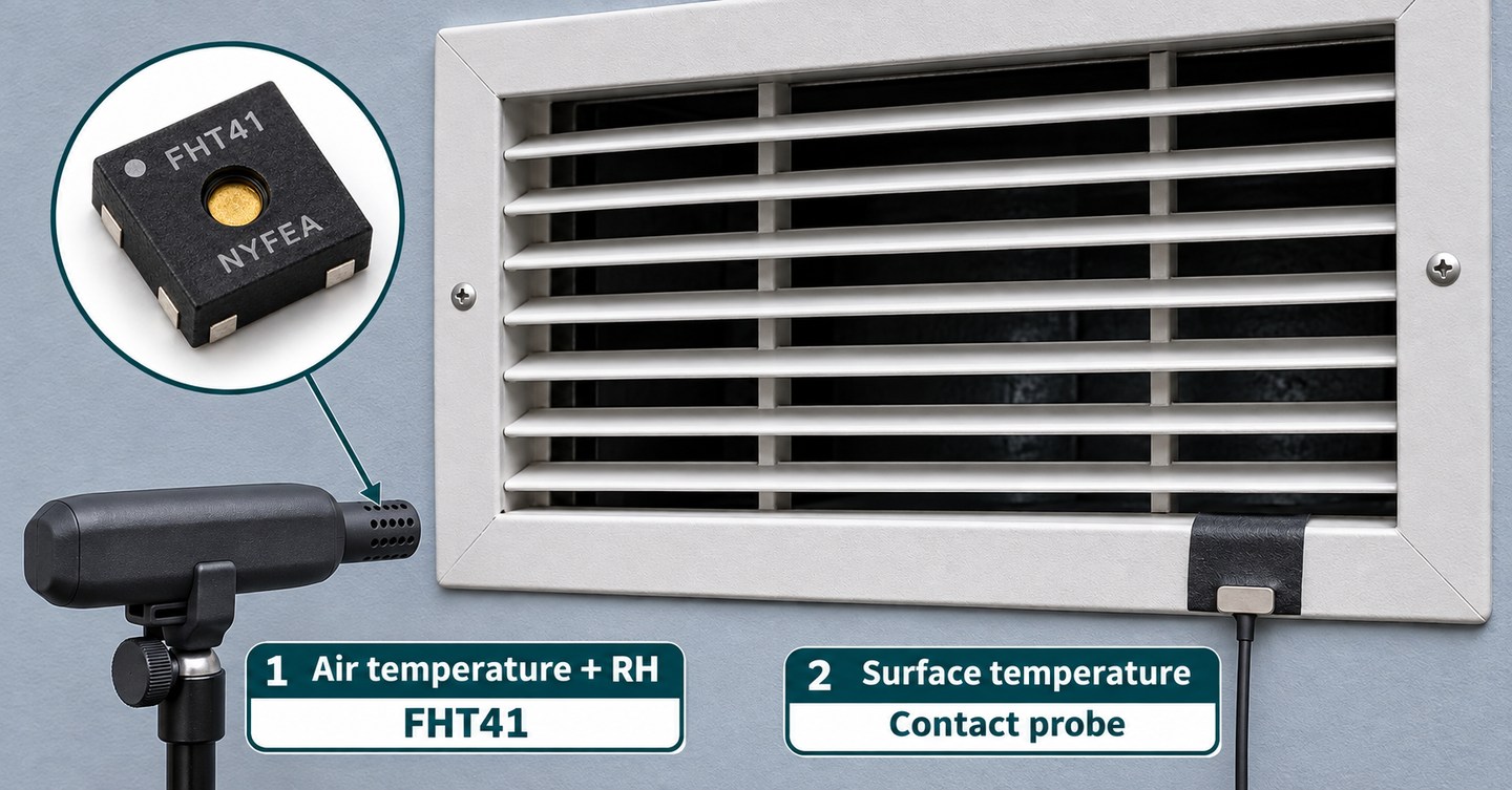
- Find the first wet spot. Mark the exact edge or panel where moisture appears. Check that the water has not flowed there from a different location.
- Measure both points together. Position the air sensor close enough to sample the relevant air while keeping it clear of the surface and droplets. Attach a contact probe to the cold spot. Give both sensors time to settle and log the readings with the same timestamp.
- Check the cycle. Start logging before cooling begins. Keep recording through startup, steady running, and shutdown. Save the lowest margin and the operating state when it occurred.
For an air-conditioning unit, use this test on a surface you expect to stay dry, such as the room-facing grille or cabinet seam. Record visible droplets at that location separately from condensate collected in the unit’s drain pan.
How do you interpret dew point margin?
Dew point margin = surface temperature − air dew point. For a surface above freezing, a negative margin indicates possible condensation under the sampled air conditions. Near zero, instrument error, probe placement and response time can change the verdict. A positive margin applies only to that place and time. Check the lowest margin over the full operating cycle before setting an alarm. ASHRAE surface-condensation reference
| What your measurements show | Next action |
|---|---|
| Margin stays below zero after allowing for error | Inspect that surface for droplets and check why it is cold or why humid air reaches it. Repeat after changing the airflow, insulation, or control setting. |
| The estimated margin could be on either side of zero | Check probe contact and air location, repeat with a reference instrument, and collect readings during the coldest part of startup. |
| Margin stays above zero after allowing for error | Review the rest of the cycle and other cold spots. If water persists, check where it first appears and inspect drainage and other moisture paths. |
Worked example with measurement error
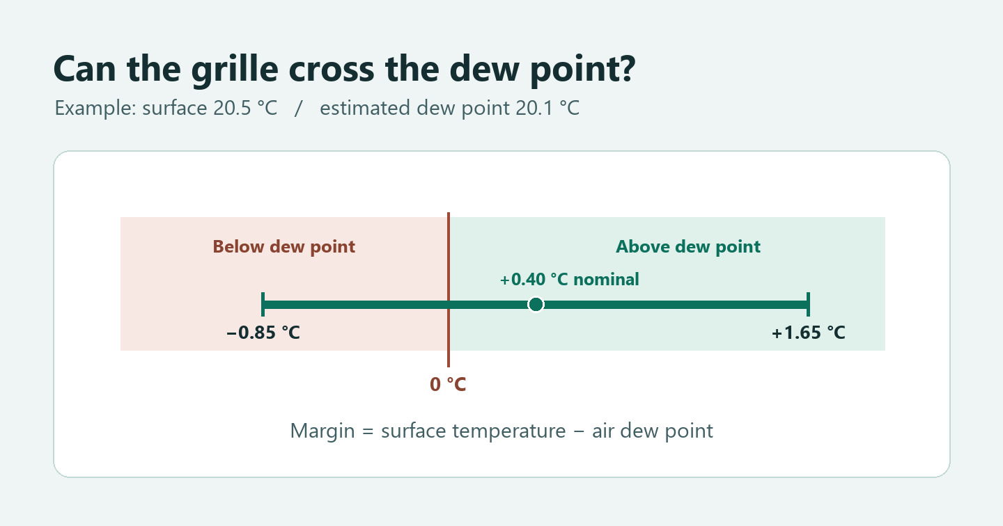
Suppose the air reads 26.0 °C ±0.3 °C and 70% RH ±2 percentage points, and the surface is 20.5 °C ±0.5 °C. Using those example input limits gives an estimated dew point of roughly 19.35 to 20.85 °C. The nominal surface margin is about +0.4 °C, but the extreme input combinations give a margin of roughly −0.85 to +1.65 °C. The margin can change sign, so repeat the measurement before using the result to set a control threshold. These are bounds from the assumed inputs. Include the effects of placement and response time separately when assessing the installed system. Vaisala calculation reference
Record one complete HVAC cycle
Copy this table into your commissioning log. Add the probe locations, reference instrument and sampling interval above it. Log the lowest margin in each phase with the timestamp and any visible moisture. Keeping the same locations and interval makes before-and-after checks more useful.
| Phase and time | Air °C and % RH | Surface °C | Dew point and margin °C | Visible moisture and location |
|---|---|---|---|---|
| Before cooling | — | — | — | — |
| Startup | — | — | — | — |
| Steady cooling | — | — | — | — |
| Shutdown | — | — | — | — |
Where does NYFEA FHT41 fit in an HVAC design?
NYFEA FHT41 is an air-side temperature and humidity sensor candidate for a new board or a second-source evaluation. Use its readings to estimate the dew point of the air that reaches the cold surface, and pair it with a separate surface probe. FHT41-TR is listed at the 7-bit I²C address 0x44, with a sensor supply range of 1.6 to 5.5 V. Check host-side I²C levels separately. NYFEA FHT41 specifications
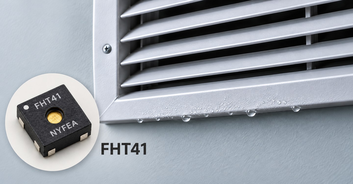
If you already have a working Sensirion SHT41 board, use it to establish your baseline. Evaluate FHT41 under the same airflow, enclosure, and sampling conditions. Verify its command timing, CRC handling and raw-value conversion against the controlled FHT41 specification before applying the dew point workflow. FHT41 communication and conversion specifications
For each assembly, record air temperature, RH, calculated dew point, the independent surface temperature and the margin. Repeat during startup, steady cooling and shutdown. Compare both candidates against the same independent air reference and surface probe, using the project’s acceptance limits. Include host-load changes and heater recovery when those occur in service.
For sample evaluation, provide the current sensor’s complete ordering code, sensor supply and I²C pull-up voltages, PCB land pattern and operating air conditions. Review the SHT41 and FHT41 evaluation steps
Dew point calculation method
The calculator uses the Magnus approximation over liquid water. Use air temperature T in °C and relative humidity RH as a percentage, such as 70 for 70% RH. The result Td is the estimated dew point in °C.
γ = ln(RH / 100) + 17.62 × T / (243.12 + T)Td = 243.12 × γ / (17.62 − γ)- Subtract the unrounded dew point from the surface temperature to get the margin.
To report a temperature difference in °F, multiply the difference in °C by 1.8. The tool uses air temperatures from 0 to 60 °C and estimates dew points within the published water-equation range of −45 to 60 °C. Vaisala dew point computation · WMO humidity equations, Annex 4.B
Questions about HVAC condensation measurements
Does SHT41 report dew point directly?
SHT41 returns temperature and relative-humidity measurements. The host calculates dew point from a validated pair of readings. Compare that estimate with a separate surface temperature measurement to assess local condensation conditions. SHT4x data format and conversion
Can an SHT41 or FHT41 measure the grille temperature?
Use the SHT41 or NYFEA FHT41 to measure air temperature and relative humidity at the air-side location. Measure the grille itself with a separate contact probe.
Can I use an infrared thermometer on a shiny metal grille?
A contact probe is the simpler reference on reflective metal. For infrared measurements, follow the instrument instructions for emissivity and spot size, and use a suitable matte target patch that has reached the surface temperature.
Fluke guidance on reflective surfaces and infrared spot size
Does water under an air conditioner always come from surface condensation?
A below-dew-point reading supports a local condensation diagnosis. Also inspect the drain path and nearby sources of water, and check whether droplets first appear at the measured surface.
SHT41 identifies a Sensirion product. FHT41 is a NYFEA product.