Sensirion SHT41 Design Options: When to Evaluate NYFEA FHT41
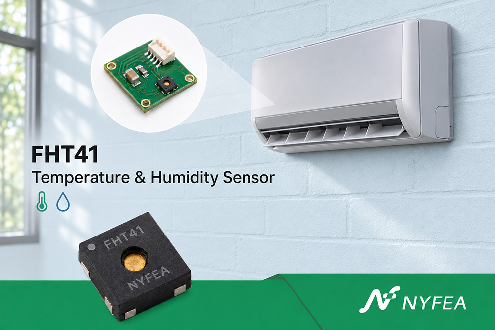
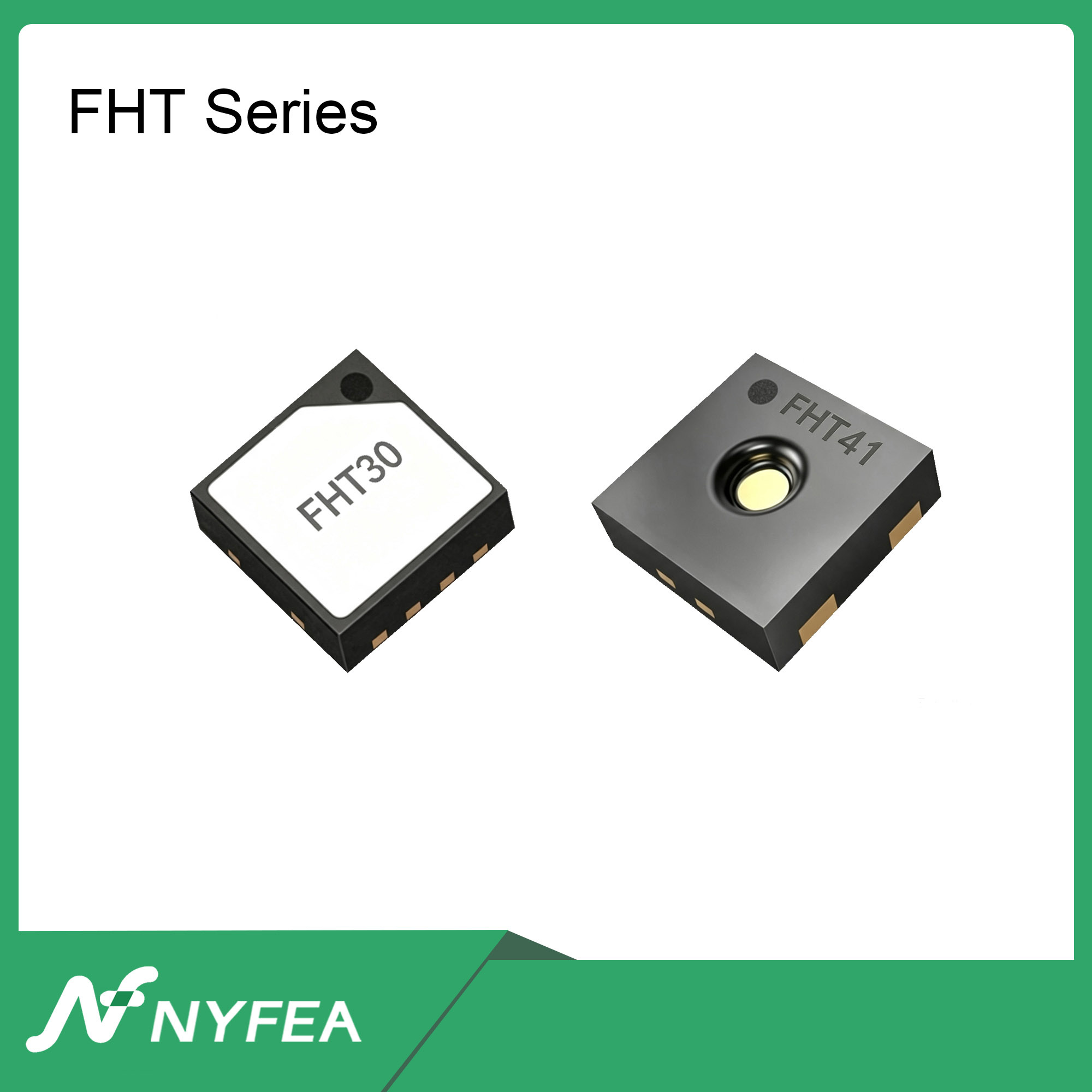
If you are selecting a temperature and humidity sensor for a design based on the Sensirion SHT41, there are three practical options. You can keep the SHT41 configuration you have already qualified, evaluate NYFEA FHT41 as a second-source candidate, or compare both devices while defining the power supply and enclosure for a new board.
For an existing design using Sensirion SHT41-AD1B-R3 at 3.3 V with the 7-bit I²C address 0x44, NYFEA FHT41-TR meets the published supply-voltage and address requirements for an initial evaluation. Before building samples on the existing PCB, review the I²C pull-up voltage, land pattern, and measurement timing. Sensirion SHT4x Datasheet V7.3 · NYFEA FHT41 Specifications
Choose an evaluation path based on your project
| Project situation | Practical option | First check |
|---|---|---|
| Qualified SHT41 design approaching production | Keep the approved ordering code. If a second source is needed, evaluate FHT41 in parallel against the existing acceptance criteria. | Confirm the exact part number, protection option, and finished-device test requirements. |
| Existing 3.3 V prototype | Add FHT41-TR to the prototype plan and establish which parts of the PCB and firmware can be reused. | Check sensor VDD, I²C pull-ups, the PCB land pattern, and the commands used by the driver. |
| New board with a 5 V rail and a 3.3 V host | Compare a 3.3 V sensor supply with a 5 V supply for FHT41 and a level-shifted I²C bus. | Check available rails, logic levels for every device, board area, and component cost. |
The full ordering code matters when the existing design relies on sensor protection. SHT41-AD1B-R3 and SHT41-AD1F-R2 both use 0x44, but Sensirion lists an integrated polyimide membrane for the AD1F variant. If that membrane is part of the approved design, include protection, humidity response, and recovery after condensation in the candidate assembly’s acceptance criteria. Sensirion SHT4x Datasheet, Table 12 · NYFEA FHT41 Ordering and Application Information
Can FHT41 run at 5 V with I²C pulled up to 3.3 V?
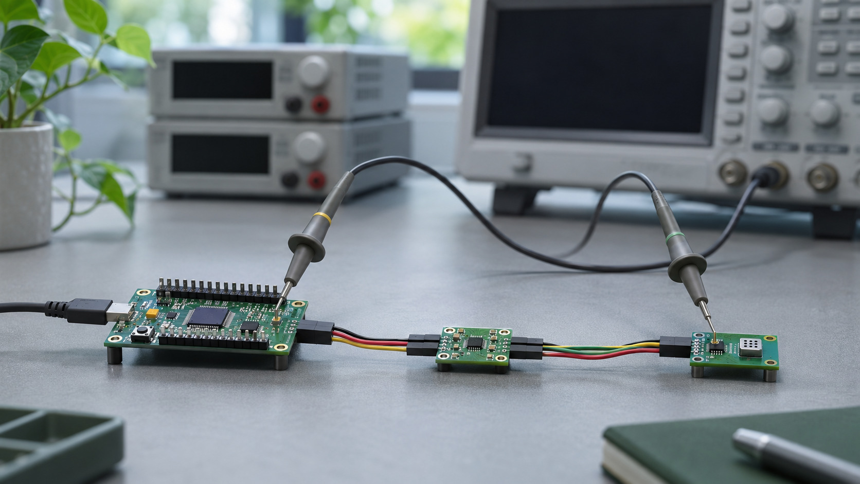
A 3.3 V pull-up falls below the published input-high threshold of FHT41 when its VDD is 5.0 V. The specification gives a minimum input-high voltage of 0.7 × VDD. At 5.0 V, that is 3.5 V. A designer choosing 5 V sensor power should account for the host-side and sensor-side logic levels in the circuit. NYFEA FHT41 Electrical Specifications
| Circuit condition | Design option to evaluate |
|---|---|
| A suitable 3.3 V rail is available and all bus devices support 3.3 V logic. | Power FHT41 at 3.3 V and pull SDA and SCL up to 3.3 V. Verify bus loading and rise time. |
| FHT41 runs at 5 V and the host uses 3.3 V I/O. | Evaluate a bidirectional I²C translator with separate pull-up rails. Check supply tolerances and rise time on both sides. |
| The standard SHT41 design is already qualified at 3.3 V. | Use the existing circuit as the baseline and evaluate FHT41 under the same electrical conditions. |
The voltage in this calculation applies at the sensor’s VDD pin. For an SHT41 breakout board, check the module input rating, its internal sensor supply, and the voltage on SDA and SCL separately. SHT41 Power and Module Wiring Guide
Both specify ±1.8 %RH typical accuracy. How should you compare them?
Both Sensirion SHT41 and NYFEA FHT41 list ±1.8 %RH typical humidity accuracy. To select a sensor for a finished device, identify the product’s operating temperature and humidity range, then check the applicable tolerance curves and their test conditions. Use the maximum error limits available for that range when preparing the device’s accuracy budget. Sensirion SHT4x Humidity Specifications · NYFEA FHT41 Accuracy Curves
For example, an indoor monitor might need to meet a defined error limit from 20 to 35 °C and 30 to 80 %RH. Mark that range on the two specifications and identify the points that need bench verification. Then test both assemblies with the same enclosure, reference instrument, and sampling interval. Record steady-state error and response time while the device is idle and while it is operating under sustained load.
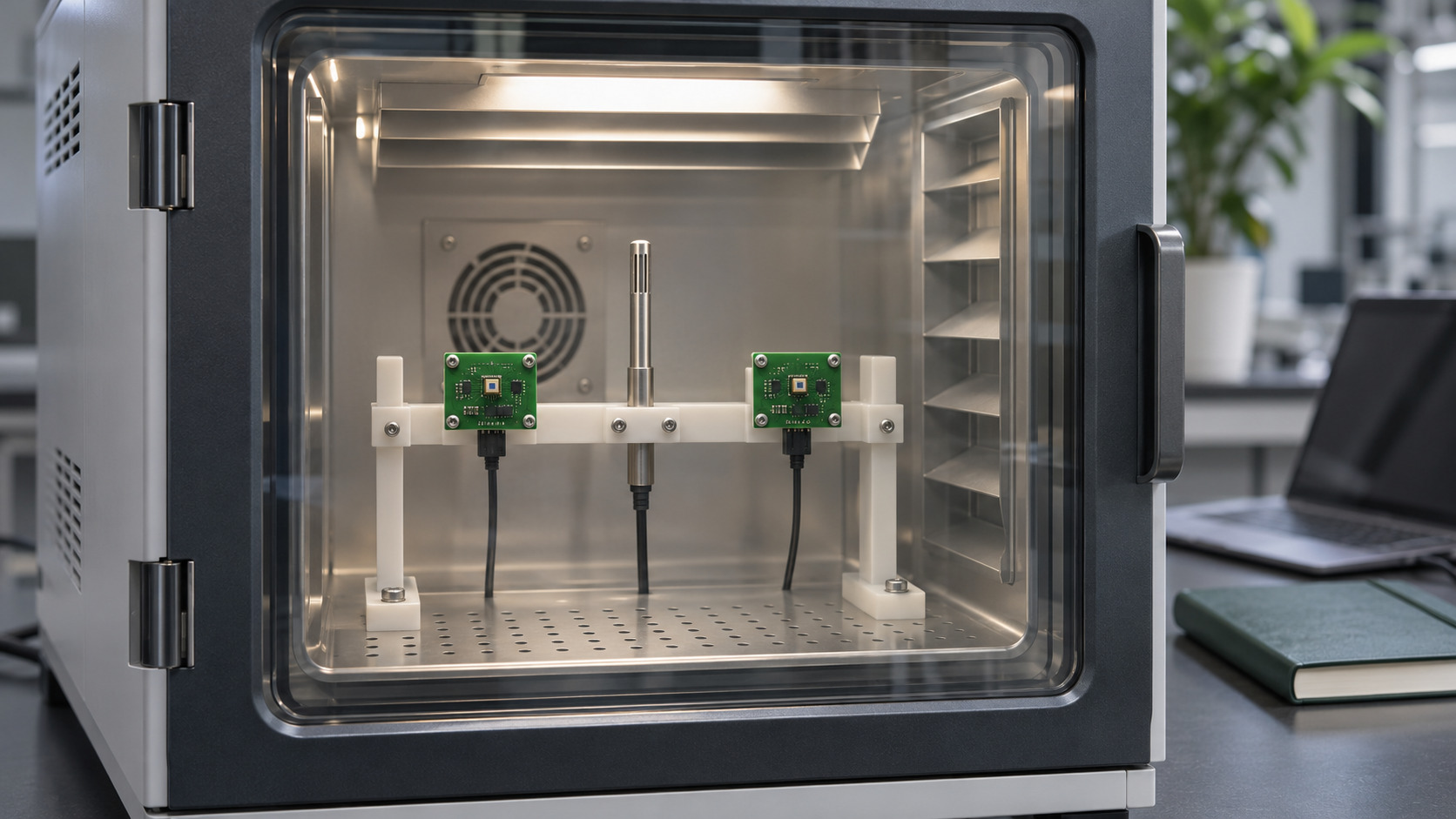
If a bias appears mainly under load, compare readings with the enclosure open and closed. This gives you a way to investigate board heat and airflow before changing the sensor or applying a software correction. If both designs meet the same finished-device criteria, compare the required circuit changes, firmware maintenance, and sourcing terms.
Can you reuse the PCB and firmware from an SHT41 design?
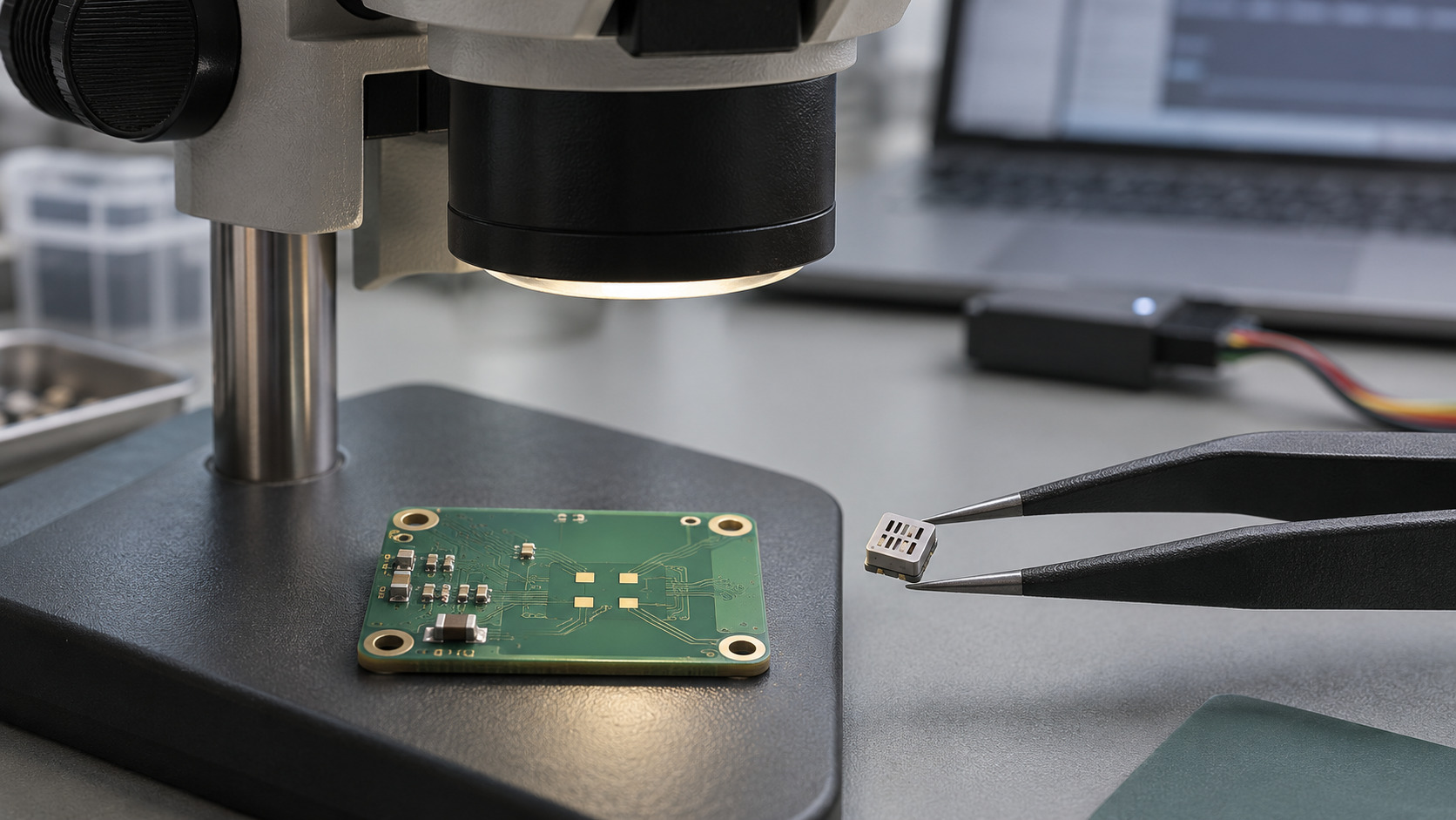
Start with the complete ordering codes, the original schematic and PCB land pattern, and a communication trace from the working SHT41 design. Use these to record what can be carried forward and what needs a drawing, circuit change, or prototype test.
| Review item | What to check | What to record |
|---|---|---|
| Supply and I²C levels | Verify VDD, pull-up voltage, logic thresholds, and the 7-bit address used by the driver. | Record whether the electrical review passed and any changes required. |
| PCB and assembly | Align pin 1 on both controlled package drawings and check the peripheral lands, exposed center area, solder mask, and stencil openings against the existing board. | Record whether the board is ready for a build or which drawing or dimension is still needed. |
| Firmware | Run the application’s commands. Check conversion wait, data format, both CRC bytes, conversion formulas, and recovery from a read failure. | Record which functions passed and which commands, timing, or retry behavior need changes. |
| Finished device | Compare accuracy, response time, and current with a shared reference instrument, enclosure design, and sampling interval. If the heater is used, record voltage droop and recovery time. | Record conditions, acceptance limits, results, and items that need further verification. |
A useful interim record for the example board is “3.3 V supply and 0x44 address passed initial screening. Existing-PCB prototype build pending land-pattern review.” That gives the hardware engineer a clear next check and tells sourcing which document to request. SHT41 Pinout, Timing, and I²C Guide · NYFEA FHT41 Package and Interface Specifications
When should you request NYFEA FHT41 samples?
If you have a working 3.3 V, 0x44 SHT41 board, start by reviewing the FHT41-TR land pattern and the measurement commands used in your firmware. For a new project, define the sensor supply, I²C pull-up voltage, and enclosure protection before selecting the prototype circuit.
When contacting NYFEA, share the existing sensor’s full ordering code, sensor VDD, I²C pull-up voltage, a drawing of the PCB lands, and the finished device’s accuracy and response-time targets. If the current design uses a membrane variant, include the enclosure and exposure requirements. These details help determine whether the next step is a drawing review, an existing-board prototype, or an evaluation on a revised circuit.